Pressure Testing Best Practices for Industrial Piping and Pressure Systems
A single undetected leak in a pressure system can cause an unexpected shutdown, a regulatory action – or worse – a catastrophic failure that endangers workers. Pressure testing is the industry’s standard way of verifying that piping, vessels and the fittings are capable of withstanding certain operating conditions before commissioning the system. This guide covers pressure testing best practices: methodology, safety precautions, equipment calibration, troubleshooting and the rules that govern all of it – so your crew can go into each test and come out with documented results that can withstand auditor scrutiny.
What Is Pressure Testing and Why Is It Needed?
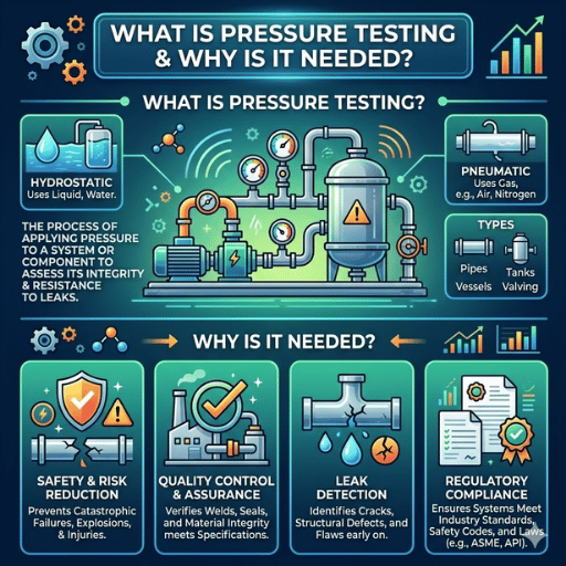
Pressure testing is a non-destructive evaluation technique used to verify the strength and leak-tightness of pressure systems—including piping systems, pressure vessels, valves, and the fittings themselves – before commissioning or following significant repairs. Pressure testing involves injecting a controlled amount of pressure into the system being tested (usually over normal operation levels) and monitoring if it will stay there without leakage, deformation or harm.
One simple assumption drives this practice: it is much safer and far more economical to identify a defective weld or a fractured fitting during a controlled pressure test than afterwards when the line carries live product. A pressure test is used to verify conformance to design specs, to check for mistakes made in the manufacture or erection of components, and to confirm that repairs were successful. Regulatory codes—ASME B31.3, API 598, HSE GS4—regard pressure testing as an essential prerequisite to any new or repaired system coming online.
In addition to remaining compliant with regulatory requirements, pressure tests are part of proper maintenance for an operating piping system. Facilities that cut corners or avoid pressure tests risk experiencing higher incidences of on-going leak events, with each incident triggering an emergency shutdown and subsequent incident investigation. Indirect costs—downtime, emergency workers, regulatory notifications—far exceed the expense of doing a test properly. $260,000+ Industry average suggests unplanned downtime in process industries costs upward of $260,000 per hour when factoring in lost throughput, emergency maintenance, and safety response overhead. 80% Field experience suggests the majority of in-service leak events trace to issues that a properly conducted pressure test would have detected at commissioning — weld defects, undertorqued fittings, and improper thread sealant application.
Pressure testing also establishes a documented baseline. When a system that has been in service for years begins to deteriorate, engineers can measure the current pressure test results against the original commissioning data to isolate the degree of change—essential information for fitness-for-service analysis. In summary, best practices around pressure testing are not administrative box-ticking. They are the bedrock of long-term safety and reliability.
Hydrostatic and Pneumatic Testing: Choosing the Right Method
Perhaps the single most important choice made in any pressure testing strategy is the selection of test medium. Hydrostatic and pneumatic testing follow similar internal-pressure logic—pressurize, hold, inspect – but the hazard profiles are strikingly different, and choosing incorrectly can be fatal.
Hydrostatic Testing
Hydrostatic testing uses water or another liquid as the test medium. Water is nearly incompressible: for the same pressure and volume, water stores roughly 200 times less energy than compressed gas. If a hydrostatic test fails—a weld cracks, a fitting blows open—the system depressurizes almost instantly, with minimal energy release. Damage is typically localized, and workers are rarely injured. Per ASME B31.3 (Process Piping), the hydrostatic test pressure is 1.5× the design pressure, held for at least 10 minutes.
Pneumatic Testing
Air or nitrogen from gas cylinders is used as the test medium during pneumatic testing. Compressed gas holds enormous amounts of stored energy – roughly 200 times more than water for equal pressure and volume. As per the PHMSA Hydrostatic Testing Fact Sheet, 200 ft. of 36 in. pipe at 500 psi holds as much energy as 80 lbs of TNT. A pneumatic test failure has the potential to produce a blast wave, pipe shrapnel, and secondary fragmentation hazards over a large area. For this reason, pneumatic testing is more hazardous than hydrostatic testing and should only be chosen under conditions where it is truly not feasible to employ a liquid, e.g. when the system is unable to be sufficiently dried, when integral supports cannot bear the weight of a water-filled line, or when the test fluid would be hazardous to the process.
Under ASME B31.3, the pneumatic test pressure may be designed at only 1.1× the design pressure (as opposed to 1.5 for hydrostatic) due the far greater risk of stored energy. As the MCAA Guide to pressure testing Safety points out, the single largest mistake made in field testing is to take the easy way out by using pneumatic testing when the much safer hydrostatic testing were equally easy.
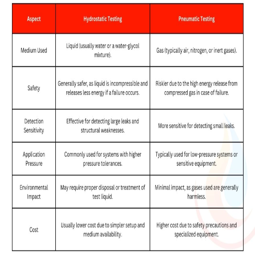
While the following table presents a comparison in general terms, the next table summarizes the main specifications differences for hydrostatic and pneumatic testing as they are relevant to process piping practices under ASME B31.3:
| Factor | Hydrostatic Test | Pneumatic Test |
|---|---|---|
| Test Medium | Water (most common) or process-compatible liquid | Air or nitrogen |
| Stored Energy | Very low (water near-incompressible) | ~200× higher than hydrostatic at same P/V |
| Risk Level | Lower — localized failure on breach | Higher — explosive decompression on breach |
| Test Pressure Multiplier (ASME B31.3) | 1.5× design pressure | 1.1× design pressure |
| Typical Applications | Process piping, pressure vessels, fire suppression lines | Instrument lines, systems where liquid is incompatible |
| ASME B31.3 Reference | Para. 345.4 | Para. 345.5 |
If you are uncertain, proceed with hydrostatic. Compared to hydrostatic testing, the added procedure in filling, venting and draining a liquid filled system is a minimal expense in the case of being proven wrong when it is implemented on a system without testing.
Pressure Testing Procedures: Step-by-Step Methodology
A reliable pressure testing procedure is what separates a test with usable data from one that cannot be trusted. The following methodology corresponds to ASME B31.3 parameters for process piping and depicts ground-verified best practices encountered during the commissioning and maintenance of industrial plant.
- Examiner the system design documentation and determine the test pressure needed. For hydrostatic testing using ASME B31.3, the smallest test pressure is design pressure, 1.5. Check each component within the test boundary for pressure ratings — the amount of pressure the test applies is only as safe as the lowest rated item within the circuit.
- Check visual condition of all knowledge placed, right way up, well secured and visible for inspection. If any knowledge must be drawn off, removed or bypassed (eg. in case of the test pressure instrument set pressure relief devices below it, or lower rated pressure instrument).
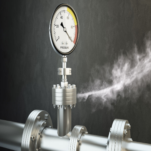
- Install calibrated pressure gauges and bleed valves at high and low spots within the system. High points must have bleed valves to remove entrained gases during filling. Low points require drain connections to depressurize in a regulated manner and drain the system after the test.
- B. Fill system with test medium (water for hydrostatic tests). Fill from lowest and vent from highest simultaneously. Make sure no air is trapped in system – air entrapment will compress and cause pressure to display incorrect readings.
- Perform a preliminary test using air at low-pressure – 25 psi (170 kPa) – to identify any major leaks prior to engaging full test pressure. Wet all fasteners and joints with soapy water and employ visual inspections during the leak test to identify bubbling. These precautions catch most systemic defectives with little risk of failure.
- Progressively ramp up pressure to test pressure in small increments – 25%, 50%, 75%, 100% – pausing for stabilization and for visual inspection. Never ramp to test pressure at once.
- Hold test pressure for a time period of not less than 10 minutes in accordance with ASME B31.3 or the governing code, if so mandated. During this period, the pressure is to be maintained steadily — observe the gauge for any settling indicating leakage or systemic deformation.
- Visual inspect all joints and connections for leaks at design pressure. Walk the full perimeter of the test systematically. Employ soapy water on threaded connections, flanged joints, and weldments.
- Retain detailed records of all test information including date, ambient temperature, test medium, quantity of test pressure reached, duration of hold, gauge calibration document number, names of inspectors, and all visual findings and indicators. This log is a legal document – regard it as such.
- De-pressurize system via the authorized valve in a safe and controlled manner, following the safety protocols specified in your test plan. Degas the complete test medium prior to system handback or return-to-service.
💡 Pro Tip: During testing procedures and in-service verification, hydraulic test points provide an effective and safe method for operators to perform diagnostic monitoring of pressure levels without disturbing flow or pressure. Hydraulic test points allow operators to connect a calibrated gauge directly into an energized line. This technique allows concurrent pressure monitoring at multiple locations, reducing reliance on single gauge locations for any single test.
Every testing procedure should be treated as a dynamic and evolving document. If any repairs or additions are made to the system during the course of the test – retorquing a leaking fitting, for example – then that section must be retested from the beginning. Partial completion is not an acceptable test report.
Safety Precautions and Personnel Protection

pressure testing involves substantial risk – even hydrostatic tests on large-bore tubing involve enough stored energy to create fatal injuries if a fitting fails. Suitable precautions are not mere padding; they are the absolute minimum standard for progression of any pressure test. OSHA’s General Duty Clause (section 5(a)(1)) hinges on the employer’s ability to protect personnel from identified hazards and HSE GS4: Safety Requirements for Pressure Testing offers perhaps the most thorough published best practice framework for how to do so.
Personal Protective Equipment (PPE)
- Face shields and goggles- compulsory for everyone who operates or is struck by the test system within the test boundary. Fine mists from High-pressure leaks can cause severe eye injuries a significant distance from the test.
- Heavy-duty gloves – obligatory to protect against pipe outbreaks and spray velocity associated with a sudden fitment failure.
- Ear protection – required in the proximity of a Pneumatic test. Sudden release of compressed gas generates impulse noise of far far greater than permitted levels of exposure.
- Hard hats and steel-toe boots – solid if you might have heavy machinery, fallen components or otherwise be subjected to sudden pipe outbreaks for any reason.
Test Boundaries and Exclusion Zones
Establish test boundaries to prevent unauthorized access and clearly mark the area ahead of pressure build up. Only those with a direct role in the test should enter the boundary while pressurizing. All non-essential personnel must be clear of the test boundary — this is particularly essential during the first pressure ramp up from 0 to test pressure, as this is more likely to cause existing faults to occur.
During pressurization, instruct all personnel to avoid standing in front of any flanged joints, valve bonnets or open pipe ends — these represent hazards to personnel if seal failure occurs. Position yourself to the side with a clear path to egress.
Pressure Relief and System Control
Never forget to place a calibrated relief valve or pressure regulator at the maximum permissible test pressure (pneumatic test circuit). Always remember that it is the final barrier that prevents excessive pressure due to pump overshoot, thermal expansion or operator error. Its set point should be checked with the system unpressurised; relief valve which is not.
Another under-estimated risk is the likelihood of brittle fracture at low temperature. Carbon steels and certain alloys have a ductile-brittle transition temperature below which they may shock, crack, rupture or shatter under stress well below the yield stress. Do not perform hydrostatic or pneumatic tests when ambient or fluid temperature reaches near the ductile-brittle transition temperature of your pipe material — there is a real possibility of brittle fracture in cold conditions. Consult the material data sheet and your project engineer before proceeding.
Common Safety Mistakes That Lead to Incidents
⚠️ Mistake 1 — Skipping the low-pressure preliminary leak check. Teams under schedule pressure often ignore the 25 psi air check and ramp straight to hydrostatic test pressure. If a major defect is present, this can lead to a high-pressure failure rather than a controlled low-energy leak at 25 psi. That check takes 15 minutes; a failed high-pressure test costs much more.
⚠️ Mistake 2 — Using uncalibrated or physically damaged gauges. A gauge with a bent Bourdon tube, cracked glass, or expired calibration certificate does not produce reliable data. The gauge can even become a projectile under test pressure. The threat from gauge failure is well known; always check every gauge before putting it in service and verify the current calibration sticker.
⚠️ Mistake 3 — Failing to establish test boundaries and exclusion zones. When test boundaries are not determined, bystanders unknowingly wander into danger zones. OSHA and HSE GS4 require an exclusion zone, either physically or by signs, prior to each pressurized test.
Equipment Calibration and Test Medium Selection
A pressure test is only as reliable as the instruments used to measure it. Calibration is no mere formality – it is what makes your test data defensible. ASME B40.100 (the relevant pressure gauges standard) mandates calibration of gauges used in a pressure testing process against standards traceable to national metrology institutes, with records of every calibration.
Calibration Intervals and Methods
The standard calibration interval for pressure gauges is at least once every 12 months. For high-stress service – in which gauges are subjected to vibration, temperature cycling, corrosive attack, or frequent pressure spikes – increase the interval to calibrate every 3 to 6 months. Any gauge that has been dropped physically or shows visual signs of damage must be pulled from service and calibrated before being put back on-line, regardless of age of last certification.
A proven method for calibrating a gauge properly is the 5-point method: apply and record readings at 0%, 25%, 50%, 75%, and 100% of the gauge full scale and compare each reading to the reference standard: errors at each point are recorded. Any gauge showing more than the allowed error at any point for its specified accuracy class must be adjusted or retired.
Temperature effects are important. At about an 18F (10C) change in ambient temperature, many Bourdon-tube gauges will experience on the order of 0.1% of reading error – not an issue when isolated but a major concern when test pressure tolerances are narrow. When ambient temperature fluctuates significantly during a test, consider the thermal effects in data analysis or retest in a stable environment.
| Equipment Type | Calibration Interval | Accuracy Class | Governing Standard |
|---|---|---|---|
| Test Pressure Gauge | 12 months (standard); 3–6 months (severe service) | Class 1.0 or better (±1% FS) | ASME B40.100 / ISO 9001 |
| Digital Pressure Transducer | 12 months | ±0.1–0.5% FS | ASME B40.100 |
| Pressure Relief Valve | Per manufacturer / annually minimum | Set point within ±3% | ASME Section VIII Div. 1 |
| Deadweight Tester (Reference) | 24–60 months (low wear) | ±0.015–0.05% FS | ASME B40.100 |
Test Point Connections and In-Line Monitoring
One often overlooked deficiency of many test setups is lack of multiple test points, an approach that addresses the impact of pressure gradients, trapped air bubbles, and valve leakage within the system. Installing a hydraulic test point along a piping circuit allows operators to connect a calibrated portable gauge directly into the live line without depressurizing or shutting down the system – a major benefit during a long holding period with frequent spot-checks needed across the system.
IKIN Fluid’s test point fittings are equipped with a patented cone seal design, rather than a standard O-ring face seal. The cone-to-cone contact between two metal sealing faces makes a leak-free connection which does not degrade over multiple connect/disconnect cycles – often very desirable when gauge connections must often be frequently made and broken. Every fitting is leak-verified before sale, important when the test point itself is part of the circuit being tested.
Test Medium Selection
For the majority of situations, water is the proper test medium for hydrostatic testing to use – it is convenient, affordable, non-compressible, and non-hazardous. If water cannot be used (oxygen service lines, food-grade piping, lines whose residual moisture would cause corrosion in service) then employ the process-compatible liquid specified by the system designer. In pneumatic tests, nitrogen is recommended over air when the system handles inflammable media — including refrigerant lines — since nitrogen is inert and won’t produce an explosive atmosphere.
Troubleshooting Common Pressure Test Failures
Most pressure test failures can be characterized by several common symptoms. Knowing the symptom-to-cause mappings in advance can save much troubleshooting labor – and ensure that false problem indications are not chased while the schedule drags on. The initial leak check at low-pressure discovers most gross defects before they result in costly repairs at full test pressure; below are failures that still will occur in a system that passes low-pressure inspection without issue.
| Symptom | Likely Cause | Corrective Action |
|---|---|---|
| Rapid pressure drop (>10 PSI in 10 min) | Missed connection, cracked pipe, or open bleed valve | Isolate sections to localize; apply soapy water to all joints and connections along the test boundary |
| Slow, steady pressure loss | Weeping joint or minor fitting leak | Depressurize fully, tighten fittings, reapply thread sealant where applicable, retest from the beginning |
| Erratic or unstable gauge readings | Air pockets trapped in piping, or damaged gauge internals | Depressurize, purge air from high points, verify gauge calibration — replace gauge if suspect |
| Test fails at design pressure (rupture or major deformation) | System design flaw, incorrect pipe schedule, or material incompatibility | Do not retest until pipe schedule, material specification, and weld quality have been reviewed against design docs; check yield strength compatibility |
| Pressure rises steadily during hold period | Thermal expansion of trapped fluid in the system | Allow thermal equilibrium before beginning the timed hold; retest under stable temperature conditions |
Never attempt to tighten fittings, make connections, alter components, or conduct any repairs while operating under pressure. Detecting leaks during a live-test is not grounds to off-line repair a pressurized joint. Shut down the system, vent and depressurize before working on any component. This represents all levels of pressure even 25 psi can be highly dangerous at close range from a suddenly venting fitting.
A working trend to watch for: if same joints and connections fail repeatedly during several in-situ tests on similar systems you can generally assume you are experiencing the effects of faulty installation too-tight flange settling, overuse of thread sealant, or excess fitting specifications. Work these irregularities up-ward to your installation team rather than treating every retest as a singular affair. Any addition or repair to affected piping that has experienced any failure effects should be fully retested — not merely the joint itself.
The most rare yet most severe failure mode is a catastrophic rupture during pressurization – most likely due to an existing crack, weld fault, or other flaw unaccounted for during visual inspection prior to testing. This is the reason the preliminary low-pressure check is so critical. The cost of a simple visual inspection investment will pay dividends in added safety and autonomy in the event of a total system failure.
Industry Standards and Compliance: ASME, ISO, and Regulatory Requirements
pressure testing is one of the most heavily codified activities in industrial plant design. Determining which code applies to hydrostatic or pneumatic testing on your system is a delicate task dependent on your manufactured item, your jurisdiction, and your defined service. An incorrect code choice can undermine your entire testing program through the administrative transfer to regulatory agencies and insurance. Presented below is a working comparison of the most relevant standards governing industrial piping and pressure systems.
Key Standards Overview
- ASME B31.3 Process Piping – The standard for all process piping operations on refineries and chemical plants etc. This standard requires hydrostatic testing at a minimum of 1.5 design pressure (Para. 345.4) with a 10 minute hold. pneumatic testing is available at 1.1 design pressure (Para. 345.5) with specified safety considerations. ASME B31.3 also stipulates an overseeing, certified supervisor of all test operations.
- ASME Section VIII Division 1 & 2 – Standard covering pressure vessel fabrication and review. Vessels must be hydrostatically tested at 1.3× maximum allowable working pressure (MAWP), pneumatically at 1.1× MAWP. Record-keeping, inspector witnessing, and acceptance criteria provisions are dictated by this standard.
- API 598 – Valve inspection and testing standard. Shell test must be within 1.5 rated-hole pressure and seat closure tests. Applicable to gate, globe, check, ball, plug and butterfly valves within API rated service.
- ISO 9001 / ASME B40.100 – Quality management, gauge calibration, and quality control requirements. ISO 9001 requires documented testing and traceable calibration records for all operations. ASME B40.100 defines accuracy class, calibration interval, and test method guidelines for all pressure gauges involved in testing activity.
- HSE GS4 (UK) – British standard safety requirements for pressure testing. Details procedures for exclusion zone infrastructure, competencies for test overseers, and required emergency controls. HSE GS4 compliance is mandated across the UK via the Pressure Systems Safety Regulations 2000 and its safety guidelines are considered global best practice.
- PHMSA / 49 CFR Part 192 & 195 (US Pipeline) – Federal mandates for natural gas and hazardous liquid pipeline testing per hydrostatic testing mandates before commissioning and following significant repairs.
Quick Reference: Key Standards Summary
| Standard | Scope | Hydro Multiplier | Pneumatic Multiplier |
|---|---|---|---|
| ASME B31.3 | Process piping | 1.5× design pressure | 1.1× design pressure |
| ASME Section VIII | Pressure vessels | 1.3× MAWP | 1.1× MAWP |
| API 598 | Valves | 1.5× rated pressure (shell) | Permitted for seat tests |
| HSE GS4 | General pressure testing (UK) | Per applicable code | Per applicable code |
| ASME B40.100 | Pressure gauges / calibration | — | — |
Two areas of compliance where teams consistently underinvest: supervisor credentials and thorough record-keeping. Adherence to ASME B31.3 requires a qualified supervisor to attend the test — not just sign off on the papers afterward. Regulators inspecting a system following an incident will request to see the test records: serial numbers of gauges, calibrations, exact duration of hold, inspector signatures. If the records are not available, the test will be considered not performed. Poor paperwork can halt operations as surely as a failed test.
Frequently Asked Questions
▸
What are the ASME standards for pressure testing?
ASME B31.3 governs process piping and mandates a hydrostatic test of at least 1.5× design pressure, along with a 10-minute hold at test pressure. ASME Section VIII covers pressure vessels and sets the hydrostatic test requirement at 1.3× maximum allowable working pressure. ASME B40.100 specifies gauge calibration for pressure testing – it defines calibration intervals, accuracy classes, and calibration methodology. Each code has its own pressure multipliers, hold durations, qualifications for inspectors, and acceptance criteria for the test. Always verify you have the current edition of the code that applies to your jurisdiction and application. ▸
Is hydrotest pressure 1.3 or 1.5 times design pressure?
Per ASME B31.3 (process piping), the answer is 1.5×. Per ASME Section VIII (pressure vessels), it’s 1.3× MAWP. Both figures appear in various codes, so the distinction matters — using 1.3× on a B31.3 system produces an undertest that inspectors and insurers may reject. Always confirm which code governs your project before locking in the test pressure. ▸
What is the ISO standard for pressure testing?
There is no single ISO pressure testing standard – the right standard depends on equipment type and sector. ISO 10432 covers subsurface safety valve equipment testing within the oil and gas sector. ISO 16528 defines test parameters for pressure vessels. ISO 9001 requires documented proof of product conformity and traceable calibration procedures for all equipment and processes regardless of application. ISO 4413 defines safety requirements for hydraulic equipment including tests. The relevant ISO pressure testing standard will depend on equipment class, application and whether the test is for initial commissioning or periodic re-qualification. ▸
Why is pneumatic testing more dangerous than hydrostatic testing?
Compressed gas contains far more energy than water at the same pressure and volume, as the gas is highly compressible while water is nearly incompressible. When a pneumatic test fails (a weld cracks, a fitting releases) that stored energy vents almost instantaneously, producing a blast wave, high-velocity shrapnel, and secondary fragmentation hazards over a wide area. Based on PHMSA data, 200 ft. of 36-inch pipe operating at 500 psi contains stored energy equivalent to 80 lbs of TNT. A hydrostatic failure would vent on the order of a small pipe spray, or localized pipe movement, not a detonation. For this reason, ASME B31.3 limits pneumatic test pressure to 1.1× design pressure, and applies more conservative exclusion zone and safeguard requirements for testing. ▸
What are the general requirements of pressure testing?
Across all major pressure testing standards, the requirements common to all include: achieving the required test pressure (using calibrated gauges traceable to national metrology standards), the test pressure hold period (minimum of 10 minutes per ASME B31.3, but for some vessel codes a much longer period), inspection of all joints and connections during the entire hold period; the use of appropriately rated control devices (valves, regulators, relief devices), the recording of test details (date, test pressure attained, hold time, gauge calibration reference, names of all inspectors, observations found); and the system being monitored under supervision from initial pressurization through final depressurization by a qualified supervisor. The test boundaries need to be defined, marked and controlled before any pressurization can commence. Conducting leak tests at low pressure before ramping to full test pressure is also a universal requirement. ▸
How often should pressure testing equipment be calibrated?
ASME B40.100 and ISO 9001 recommend pressure gauge calibration at a minimum interval of 12 months for normal operating conditions. In more extreme operating conditions such as continuous vibration, extreme temperature, corrosive environment, or high cycle time for pressure fluctuation, calibrate every 3 to 6 months. Any gauge that is dropped, physically struck, or sustained mechanical damage shall be removed from service, and calibrate before use again irrespective of the testing schedule. The proper procedure is the 5-point calibration method: apply pressure at 0%, 25%, 50%, 75%, and 100% of the gauge full scale and record the error at each point using an industry traceable standard. Calibration certificates must be retained in the test records.
Need Reliable Pressure Test Points for Your Next Project?
IKIN Fluid has manufactured hydraulic test points and precision fittings since 2009. Our patented cone seal design delivers leak-free connections that hold up to repeated connect/disconnect cycles in demanding test environments — backed by 100% leakage inspection and a 3-year warranty. Trusted by 3,000+ industrial partners across global markets.Explore IKIN’s test point solutions →
Editorial Disclosure: This article was prepared by the engineering team at IKIN Fluid based on published industry standards (ASME, ISO, API) and field experience from over 15 years of manufacturing hydraulic test components. While authoritative sources have been referenced throughout, pressure testing requirements vary by jurisdiction, equipment type, and operating conditions. Always consult your project’s governing code and a qualified engineer before performing pressure tests. IKIN Fluid manufactures hydraulic test points and fittings — we do not provide engineering certification or code compliance consulting.
References & Sources
- OSHA Standard Interpretation: Pressure Testing Using Compressed Air (May 1996)
- HSE GS4: Safety Requirements for Pressure Testing – Health and Safety Executive (UK)
- MCAA: Guide to Pressure Testing Safety – Mechanical Contractors Association of America
- PHMSA: Hydrostatic Testing Fact Sheet – Pipeline and Hazardous Materials Safety Administration
- INGAA: Guidance for Pressure Testing – Interstate Natural Gas Association of America
- EIGA DOC 254: Guideline for Pressure Testing of Field-Installed Piping – European Industrial Gases Association