How to Choose the Right Microbore Test Hose for Hydraulic Pressure Diagnostics
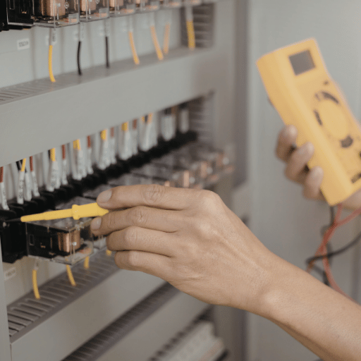
A single wrong hose selection can mean the difference between a pressure reading you can rely on, and a blow-out at 9,000+ PSI. Microbore hydraulic test hoses are the thin link that connects your gauge or transducer from a live hydraulic system – getting this wrong costs money, time, and possibly lives.
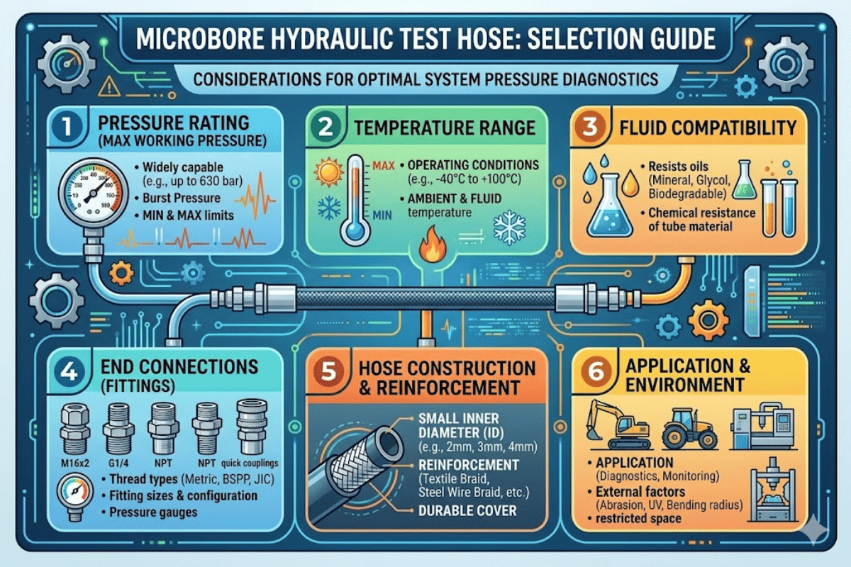
This guide is designed to give a hydraulic maintenance professional or procurement engineer all the details they need to know before selecting a microbore hydraulic test hose: bore sizes, pressure ratings, fitting type, installation failures and the best assembly choices
What Is a Microbore Hydraulic Test Hose and Why Does It Matter?
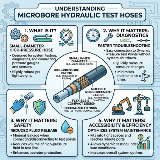
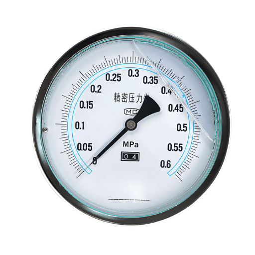
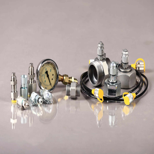
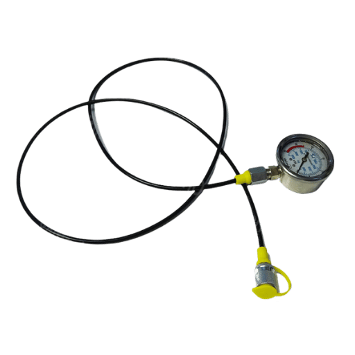
A microbore hose is a small-diameter high-pressure flexible hose design designed specifically for diagnostic work on hydraulic pressure. With an internal diameter of just 2mm (DN2) or 4mm (DN4), these hoses are used to connect pressure test points on the machinery to gauges, transducers or data loggers located externally – enabling field technicians or survey engineers to read pressure without opening up the primary fluid
Why the small bore? It limits the amount of live fluid exposed to the external environment. This results in quicker pressure response at the gauge, decreased risk of catastrophic failure (should the hose fail), and while connecting and disconnecting it means less fluid is expelled into the environment. 2mm DN2 Internal Bore 630 bar Max Working Pressure 4:1 Min Safety Factor (SAE)
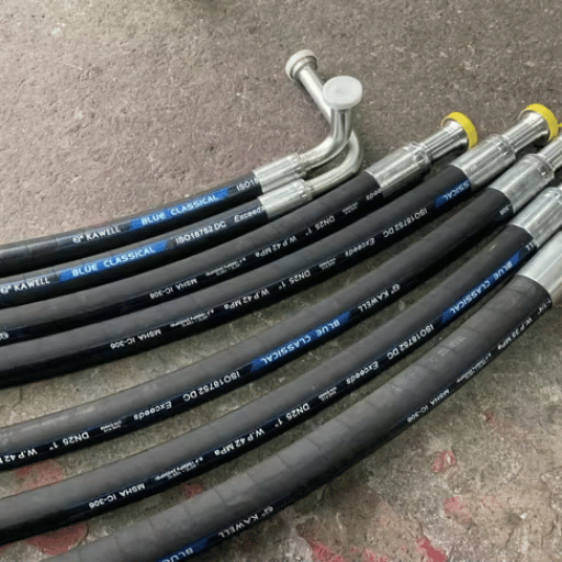
Microbore test hoses are fabricated from a polyamide inner core, with a synthetic fiber braid reinforcement and polyamide outer jacket. This provides a reliable, durable product while also being capable of working pressures of 630 bar (9,100 PSI). With this construction in mind, we have seen the demand for DN2 microbore hose assemblies steadily increase since we first started supplying OEMs such as Parker and Eaton in 2009 – particularly in mobile field applications involving pressure testing. 💡 Pro Tip The shop-floor term ‘spaghetti hose’ is a reference to microbore hose products’ slim and flexible profile. You may also see minimess hoses, micro bore hoses, or test point hoses in our catalog.
DN2 vs DN4: Choosing the Right Bore Size for Your Application
Bore size is the first consideration when choosing a microbore hose assembly. DN2 (2mm internal diameter) and DN4 (4mm internal diameter) have different applications and operating abilities. Picking wrong means either over-specifying (wasting budget) or under-specifying (risking a failure).
| Specification | DN2 (2mm Bore) | DN4 (4mm Bore) |
|---|---|---|
| Internal Diameter | 2mm (0.078 in) | 4mm (0.157 in) |
| Outer Diameter | 5mm (0.197 in) | 8mm (0.315 in) |
| Working Pressure | 400–630 bar (5,800–9,100 PSI) | 315–450 bar (4,570–6,525 PSI) |
| Burst Pressure | 1,040–1,950 bar (15,100–28,300 PSI) | 810–1,500 bar (11,750–21,750 PSI) |
| Min. Bend Radius | 20mm | 40mm |
| Temperature Range | -20°C to +100°C (standard) -54°C to +100°C (low-temp variant) | -20°C to +100°C |
| Best For | High-pressure diagnostics, tight spaces, mobile equipment | Higher flow sampling, oil analysis, lower-pressure systems |
DN2 hose assemblies have been long established in pressure diagnostics, with the compact 5mm outer diameter fitting through cable trays and parity with existing hose effectively. For high pressure system applications, (over 450 bar) the DN2 with the new 630 bar rated variant is the only microbore choice that fulfills the working pressure requirement.
DN4 hose assemblies are better suited if you need to take fluid samples for analysis, or if the hose are running to a larger port on a microbore hose assembly gauge. A bigger bore allows for a more rapid transfer of fluid, which matters for flow-based measurements.
- ✔ Choose DN2 for pressure-only diagnostics above 315 bar
- ✔ Choose DN2 for tight routing while maintaining a 5mm OD
- ✔ Choose DN4 for oil sampling or flow-based measurements
- ✔ Choose DN4 for connections where a lower pressure operation is desired and flow rate is less critical
Both bore sizes are available in DN2 microbore hose assemblies with various end fittings pre-assembled and pressure-tested at the factory.
Pressure Ratings and Working Limits You Need to Know
Every hydraulic pressure test hose carries three pressure numbers that determine whether it is safe for your application: working pressure, proof (test) pressure, and burst pressure. Misunderstanding these values is one of the most frequent errors we encounter in the field.
| Pressure Type | DN2 (630 bar rated) | Definition |
|---|---|---|
| Working Pressure | 630 bar / 9,100 PSI | Maximum continuous operating pressure — never exceed this in service |
| Proof Pressure | 950 bar / 13,780 PSI | Factory test pressure (approx. 1.5× working). Used to verify no leaks or deformation |
| Burst Pressure | 1,950 bar / 28,300 PSI | Destructive failure point. Must be ≥4× working pressure per SAE J343 |
The 4:1 safety factor ratio — burst pressure divided by working pressure — is the industry minimum established by SAE standards. According to Power & Motion’s hose testing guidelines, proof tests apply pressure up to 2× the maximum allowable working pressure (MAWP) to verify the assembly will not rupture or leak, while burst tests require a minimum of 4× MAWP to pass. ⚠️ Important Never use a microbore hose rated at 400 bar on a system operating at 500 bar — even if the burst pressure exceeds your system pressure. The working pressure rating already accounts for fatigue, temperature derating, and impulse spikes. Exceeding it, even briefly, accelerates hose degradation and voids the manufacturer’s warranty.
For environments below -20°C — think outdoor winter testing in northern climates — a low-temperature DN2 variant rated to -54°C is available. Standard polyamide hose stiffens significantly below -20°C, which increases the risk of cracking at bend points. IKIN supplies high-pressure test hose with M16x2 connections in both standard and low-temperature configurations.
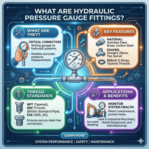
Microbore Hose Fittings and Connection Types
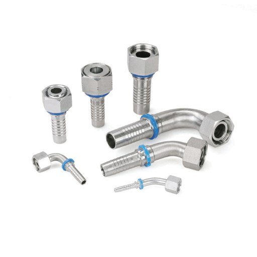
Selecting the right hose is only half the equation. Microbore hose fittings determine whether your test hose connects safely to the test point on one end and the gauge or transducer on the other. A mismatch here — wrong thread, wrong seal type — leads to leaks, inaccurate readings, or damaged ports.
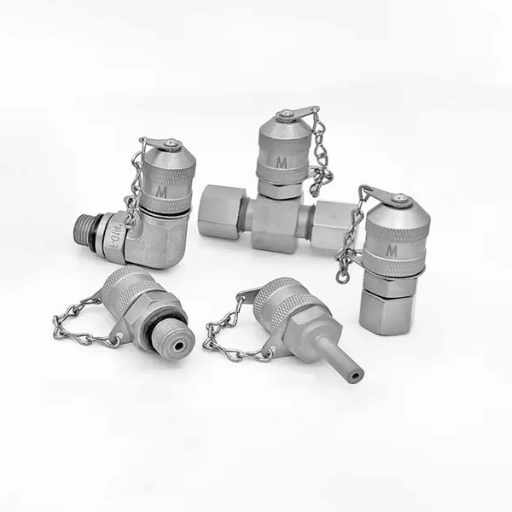
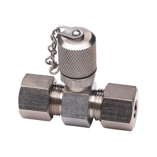
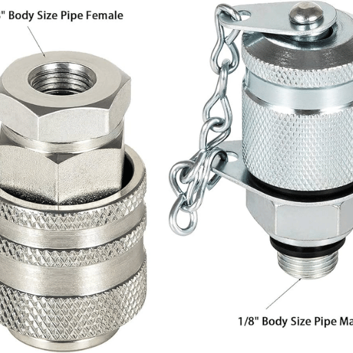
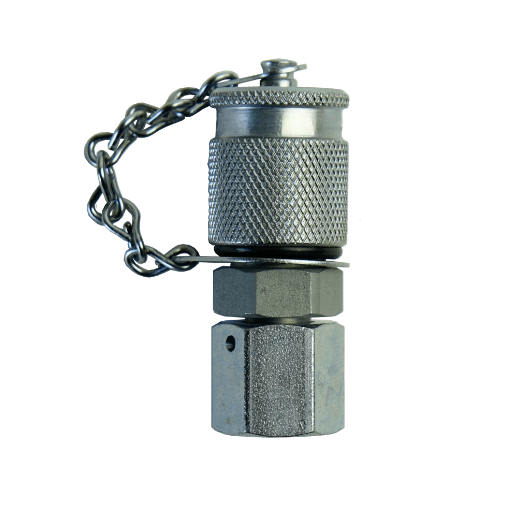
The M16x2 Standard (Test 20 / Minimess)
M16x2 has become the de facto standard for hydraulic test point connections worldwide. You will see it called by different names depending on the manufacturer — Minimess (STAUFF), Test 20, MiniPress — but the thread pitch and sealing design are interchangeable across brands.
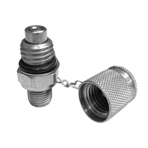
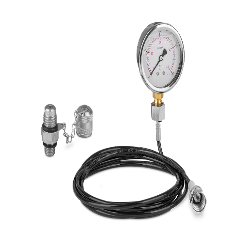
On the test-point side (the port installed permanently in the hydraulic system), the M16x2 coupling connects up to 400 bar (5,800 PSI) and includes a built-in check valve. This check valve is a key safety feature: it prevents fluid from escaping when the test hose is disconnected, keeping the work area clean and reducing the risk of high-pressure fluid injection injuries.
Gauge-Side Connection Options
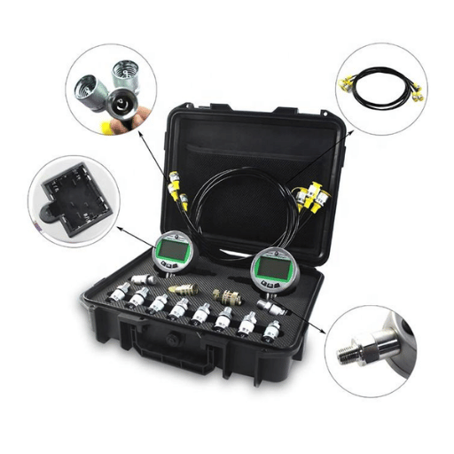
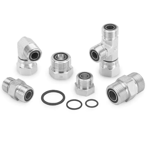
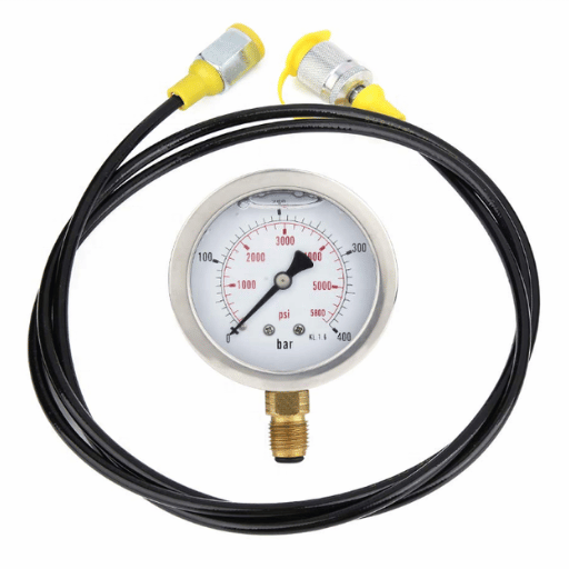
While one end of the microbore hose assembly typically terminates in an M16x2 female fitting, the other end — connecting to your gauge, transducer, or data logger — comes in multiple thread standards:
| Thread Type | Common Sizes | Seal Method | Typical Use |
|---|---|---|---|
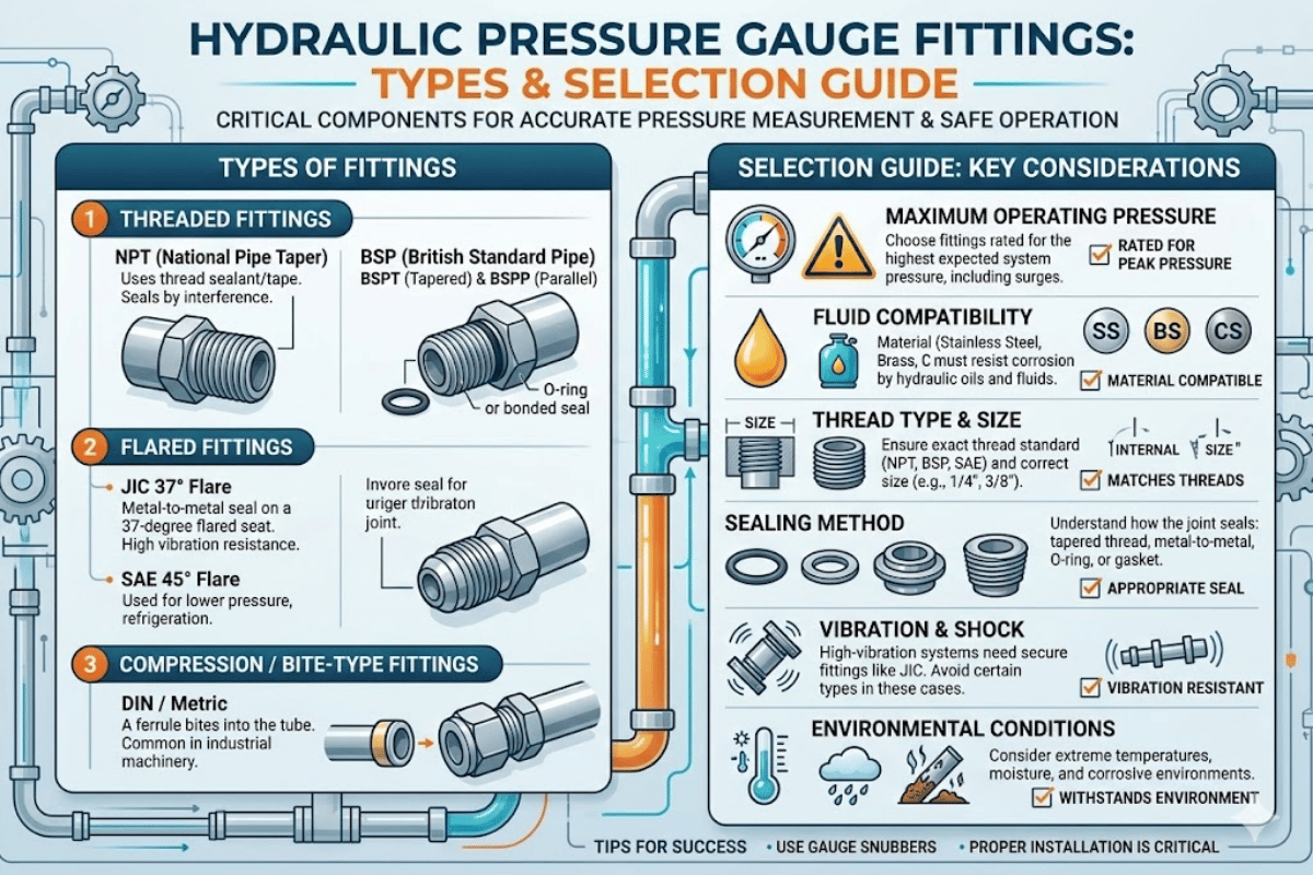
| NPT (National Pipe Thread) | 1/8″, 1/4″, 3/8″, 1/2″ | Tapered thread + sealant | North American gauges, US-made equipment |
| BSPP (British Standard Pipe Parallel) | G1/8, G1/4, G3/8 | Bonded seal / washer | European gauges, UK/EU equipment |
| JIC (SAE J514) | #4, #6, #8 (37° flare) | Metal-to-metal flare | US mobile hydraulics, construction equipment |
| ORFS (O-Ring Face Seal) | SAE #4, #6 | O-ring on flat face | Leak-free applications, high-vibration |
| Metric (DIN) | M14x1.5, M18x1.5 | Bonded seal or washer | German/European OEM equipment |
| Pipe to Pipe (Female-Female) | NPT or BSPP both ends | Per thread type | Gauge-to-gauge transfer, extensions |
Before ordering, check the thread on your gauge port with a thread identifier gauge or caliper. A 1/4″ NPT male and a G1/4 BSPP male look nearly identical but are not interchangeable — cross-threading them damages both the fitting and the gauge port. IKIN manufactures hydraulic test hose fittings in all six thread types listed above, with steel and stainless steel material options.
How to Select the Correct Hose Assembly for Your System
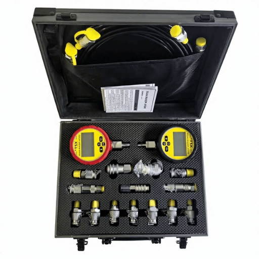
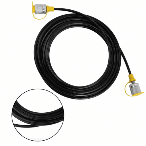
Once the bore size, pressure rating and fitting type are settled, the final step is the selection of the correct hose assembly configuration. microbore hose is available in various lengths — from 250mm (10 inch) to 3,000mm (10 ft) assemblies for reaching test points on large mobile machinery.5-Step Hose Assembly Selection Method
- Determine your system maximum operating pressure (check relief valve setting not pump rating), and add 10% to account for pressure spikes.
- Calculate the distance from test point to gauge mounting position, and add 15-20% for routing slack; the hose under tensile strain at a sharp bend will fail early.
- Determine the connection threads, test point thread (generally M16x2) and gauge thread (NPT, BSPP, JIC or other).
- Check the operating temperature range, generic polyamide hose is rated for -20C to +100C; colder climates and hot engine compartments may need a special type.
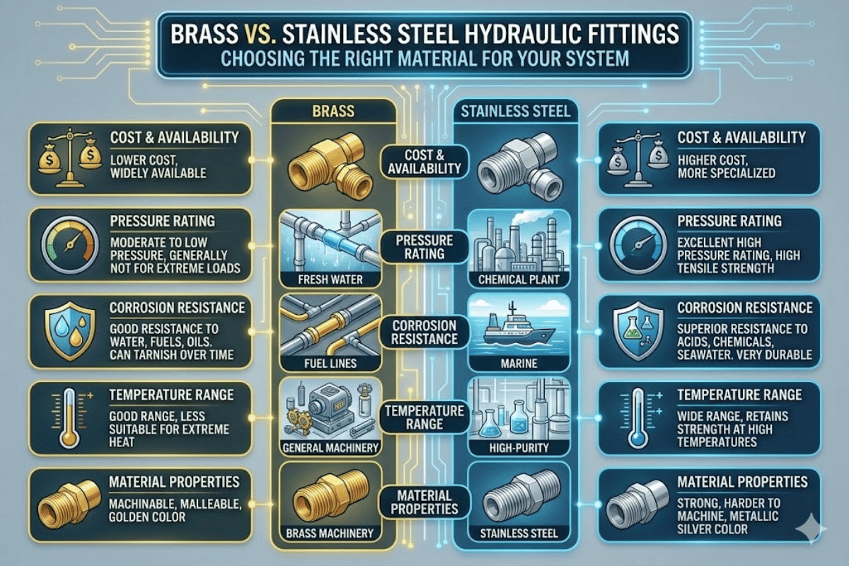
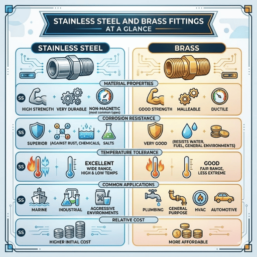
- Material decision; fittings in mild steel for normal service, a stainless type for corrosive environment or offshore/marine use.
Our team at IKIN can process orders at a competitive price with a low minimum order quantity, ideal for maintenance departments that need to purchase a small kit of 3-5 hose assemblies, each with a different length but not needing a high-volume order of a single size. Every assembly is supplied with 100% leakage inspection certificate, a requirement we are proud of as one failed fitting at 630 bar is not only irritating but a safety risk.
Custom hose assemblies in any variety of lengths and end-fittings are designed for specific applications; IKIN stocks a wide selection of microbore hose lengths and configurations and standard delivery within 10 working days for bulk orders.
Installation Best Practices and Common Mistakes to Avoid
While a correctly specified microbore hose assembly can fail from improper installation, field experience from our network of 3,000+ technicians across industrial hydraulics, construction equipment, and mobile machinery reveals that three installation mistakes are primarily responsible for premature hose failures. ⚠️ Three Mistakes That Cause Most Microbore Hose Failures
- Failure to respect the minimum bend radius. hose with a 20mm minimum bend radius (DN2) will kink at about the diameter of a standard US quarter; bending it too tight crushes the inner tube and creates a weak point.
- Cross threading the M16x2 test point. The fine-pitch (2mm pitch) M16x2 thread on the test point must not be inclined of axis as hand-starting in 1-2 turns will pulverize the thread. Never use a wrench to tighten beyond specified torque rating.
- Leaving a hose attached to a machine under pressure; the definitive specification for diagnostic use only. Microbore hose is not for “permanent plumbing”. pressure stress cycles from pump on/off commands accelerate depressurization fatigue. Unplug the hose after every test session.
Recommended Installation Steps
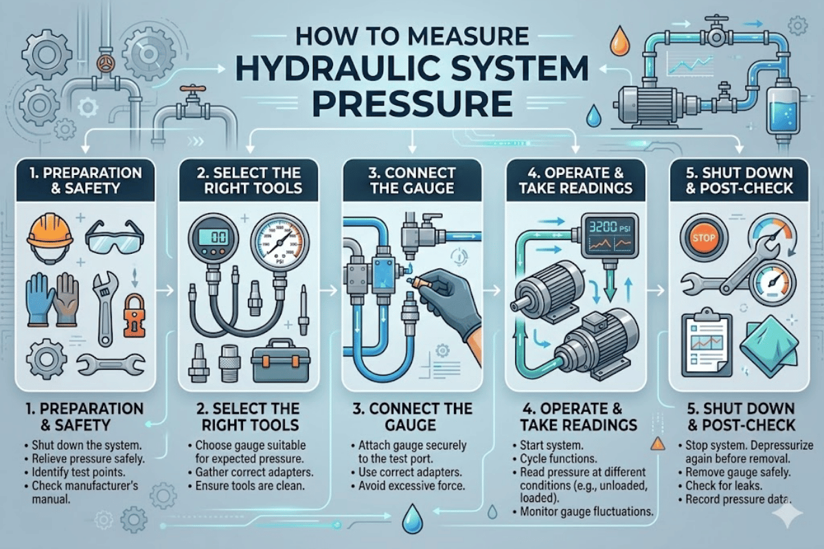
- Relieve the hydraulic system pressure and confirm that no pressure is present in the pipework. The OSHA Hazard Information Bulletin on Hydraulic Systems Preventive Maintenance requires that all stored hydraulic energy be relieved before making or breaking connections.
- Clean the test point and hose fittings with a lint-free wipe. contamination is the number one cause of system damage — industry data indicates that roughly 80% of hydraulic system failures involve fluid contamination or hose failure.
- Hand thread the M16x2 coupling through the test point, and finger tight. If it is going onto a female connector then quarter turn with the correct wrench size. Avoid an adjustable wrench as it rounds the hex, and compromises future connections.
- Route the hose away from free moving components, abrasive surfaces or heat sources. Secure with cable ties or clamps at 300mm maximum for runs greater than 500mm.
- Ensure the system is pressurized slowly and leaks are checked at both ends before reading.
- After testing, depressurize and disconnect, then cap both the test point and hose ends to prevent contamination ingress.
Inspection Schedule
As specified by OSHA 1926.302, the manufacturer’s maximum operational pressures for hoses shall not be surpassed and all hoses will be examined at a determined frequency for signs of degeneration. Our specific recommendations for microbore test hoses are:
- Before each use — visual check for kinks, abrasion, swelling, or fitting damage
- Quarterly (stationary equipment) – length inspection under daylight conditions
- Each 400-600 hours operation (mobile equipment) – detailed inspection and proof-pressure test
- Annual replacement regardless of condition, for hoses used at daily service
💡 Pro Tip Number every microbore hose assembly with the date in which it was first used using a permanent marker on the fitting hex. This makes it simple to monitor service life without any spreadsheet or logbook – and it is the first thing an auditor will ask for during a safety inspection.
Frequently Asked Questions
Q: What is the maximum working pressure for a microbore test hose?
View Answer Max loading of 630 bar (9,100 PSI) for Standard DN2 microbore test hose. Max loading of 450 bar (6,525 PSI) for DN4. See individual model datasheet for rated working pressures, different materials have different maximum limits, ratings are also affected by temperature.
Q: Can microbore hoses be used with gas as well as hydraulic fluid?
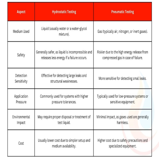
View Answer Yes, microbore hoses use liquid media (hydraulic oil, water-glycol) and gases ( nitrogen, compressed air) for pressure testing. Gas testing is much more dangerous. Gas is compressible, so the stored energy in a hose failure is released explosively rather than slowly trickled. Liquid testing is safer because liquids are nearly incompressible, so a breach produces a jet not a blast. If you must test with gas, conduct a detached blast shield around the hose run, verify the hose material specs for that particular gas, lower the test pressure Ramp Rate, and remain well clear of the hose path. OSHA handles compressed gas differently from hydraulic fluid for this reason.
Q: How often should microbore test hoses be inspected or replaced?
View Answer Inspect microbore test hoses regularly before each use for kinks, cracking, swelling, or fitting damage. Conduct a thorough inspection every 3 months if stationary, or every 400-600 hours if mobile. Annually replace hoses that are used on a daily basis for diagnostic service. The polyamide core loses its integrity with prolonged UV exposure, pressure cycling, chemical exposure, even if shell looks intact.
Q: What is the difference between Minimess and standard test point connections?
View Answer Minimess is a brand name for a test point coupling, dimensions wise an M16x2. Similar thread has also been marketed under names like Test 20 or MiniPress. They are compatible.
Q: Are microbore hose assemblies available in custom lengths?
View Answer Yes. Most job houses in standard microbore hose assemblies offer the usual lengths, frequently from 250mm-3000mm, and most builders including IKIN fluid will custom-build lengths with any required end-fitting combinations. Custom assemblies are often specified for OEM use; the modular configuration makes it easier to build an assembly that follows a precise routing path in an encased machine. The typical lead-time for custom orders is 10-15 working days depending on fitting combination and order size.
Q: What hydraulic fluids are compatible with microbore test hoses?
View Answer Standard polyamide microbore hoses are suitable for mineral hydraulic oils (ISO VG 15-68), poly-alpha-olefins (PAO), water-glycol fluids and nearly all phosphate ester fluids. Relative to mineral oil systems, they are not recommended for use with concentrated acids, concentrated alkaline solutions or aromatic solvents. For highly corrosive systems and fitting extremes, a PTFE-lined stainless steel braided version (DN2, rated to 450 bar) provides a broader chemical resistance and can operate between -70C and +260C.
Need Microbore Test Hoses for Your Operation?
IKIN fluid manufactures DN2 and DN4 microbore hose assemblies with 100% leakage testing, a 3-year warranty and a 10 working day delivery period. Low MOQs accepted. Browse IKIN’s Hydraulic Test Hose Catalog →
About This Guide
This technical guide was prepared by the IKIN fluid consulting engineering team, based on over 15 years of manufacturing hydraulic test points, microbore hose assemblies and pressure gauge connectors for clients including Sany, Hawe Hydraulic and Bucher. Technical specifications cited can be found in published manufacturer datasheets, SAE standards and OSHA safety bulletins–not AI-derived estimates. If we also recommend our own products, we say so explicitly.
References & Sources
- Hydraulic Systems Preventive Maintenance (Hazard Information Bulletin) — U.S. Department of Labor, OSHA
- OSHA 1926.302 — Power-Operated Hand Tools — U.S. Department of Labor, OSHA
- SAE J343 — Test and Test Procedures for SAE 100R Series Hydraulic Hose — SAE International
- SAE J1273 — Selection, Installation and Maintenance of Hose and Hose Assemblies — SAE International
- Guidelines for Conducting Hose Testing — Power & Motion