How to Troubleshoot Hydraulic Systems Using Test Points
A hydraulic system that stops performing costs money every minute it sits idle. Industry reports put unscheduled downtime at $1,000 to $5,000 per hour depending on the application. Yet most hydraulic failures leave clues long before a full breakdown — if you know where to look. That is exactly what hydraulic system troubleshooting with test points delivers: a fast, repeatable way to diagnose pressure drops, leakage, contamination, and valve malfunction without tearing equipment apart. In this guide, we walk through the full process — from identifying common hydraulic failures to reading pressure test results and building a preventive monitoring routine around strategically placed hydraulic test points.In This Guide
- Why Troubleshooting Starts at the Test Point
- Common Hydraulic Failures and Their Root Causes
- Diagnostic Tools for Hydraulic Pressure Testing
- Step-by-Step Hydraulic Troubleshooting with Test Points
- How to Read and Interpret Pressure Test Results
- Preventing Failures with Routine Monitoring
- Where to Install Test Points for Maximum Coverage
- FAQ
Why Hydraulic System Troubleshooting Starts at the Test Point
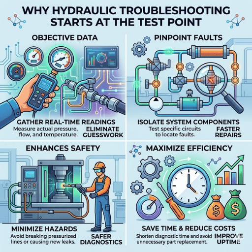
Hydraulic system troubleshooting is the process of identifying and isolating the root cause of system performance loss — whether that means low pressure, sluggish cylinder movement, excessive heat, or unusual noises — before committing to expensive component replacements. The key tool in this process is the test point: a small port installed at critical locations throughout the circuit that allows a pressure gauge or flow meter to be connected without disassembling anything.
Without test points, diagnostics become guesswork. Field data from maintenance organizations consistently shows that roughly 60% of premature hydraulic component swaps — pumps, valves, motors — turn out to be unnecessary. The real issue is often a clogged filter, a worn seal, or incorrect pressure settings on a relief valve. A pressure test in the proper place shows the cause in minutes, not hours. 75% Of hydraulic failures trace back to fluid contamination 3–5× Higher cost of reactive vs. preventive maintenance 60% Of component swaps later found unnecessary
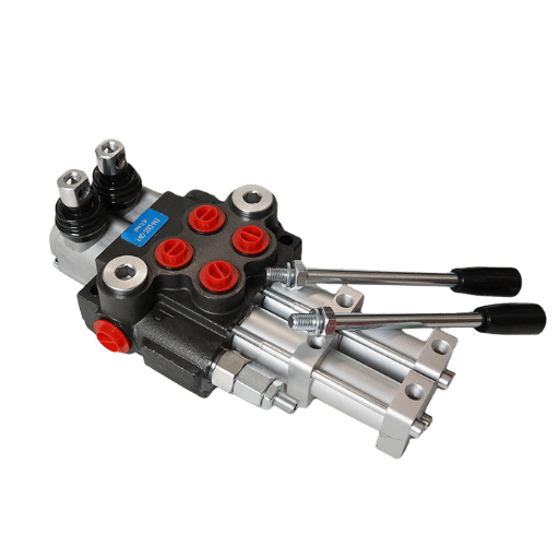
Installing test points at the hydraulic pump outlet, directional control valve ports, cylinder lines, and return line transforms the troubleshooting process from a reactive scramble into a structured, data-driven process. Every reading narrows the fault down to a specific subsystem, helping reduce system downtime and budget waste. On larger rigs, a permanently mounted pressure gauge to monitor pump output around the clock removes the need for repeated manual hookups.
Common Hydraulic Failures and How to Identify Their Root Causes
First, before you hook up a gauge to any hydraulic test port; you will need to identify which symptoms to look for and the hydraulic problem each symptom represents. Most hydraulic failures are a manifestation of a handful of causes, and each one gets you a different diagnostic fingerprint at the test point.
According to Noria Corporation’s contamination research, at least 75% of all hydraulic system failures trace back to contaminated or degraded hydraulic oil. New hydraulic fluid straight from the drum can contain approximately 500,000 particles per 100 ml above 5 µm — already exceeding most manufacturer cleanliness specs. Once in service, ingressed dirt, water, and wear metals accelerate seal degradation, valve spool scoring, and pump wear.
| Symptom | Likely Root Cause | Test Point Action |
|---|---|---|
| Slow cylinder movement | Internal leakage in pump or cylinder; relief valve set too low | Measure system pressure at pump outlet and cylinder ports |
| Overheating hydraulic fluid | Excessive internal leakage; clogged cooler; wrong viscosity oil | Check pressure drop across the cooler; compare inlet vs outlet temps |
| Unusual noises (whining, banging) | Cavitation at pump inlet; air in the system; loose fittings | Read vacuum at pump inlet; inspect reservoir level and hose connections |
| No movement at all | Motor or pump failure; electrical fault; directional valve stuck | Confirm pressure at pump outlet; if zero, check motor coupling |
| Erratic or jerky operation | Air ingestion; contamination in control valve spool | Monitor pressure oscillation at control valve test port |
| External leakage at fittings | Worn seals; over-tightened or under-tightened fittings; hose degradation | Visual inspections first; then pressure test to confirm leak rate |
⚠️ Common Mistake Replacing a hydraulic pump because the cylinder moves slowly — without first checking whether the relief valve is set below maximum system pressure. A five-minute pressure test at the pump outlet test point would have revealed the real issue and saved a $2,000+ pump replacement.
Diagnostic Tools You Need for Hydraulic Pressure Testing
The key to effective hydraulic troubleshooting techniques lies in matching the right tools to the task. The three essential diagnostic tools flow meter, hydraulic analyzers, pressure gauges – fill three different functions that are frequently combined on a single hydraulic test port.
| Tool | What It Measures | Accuracy | Best For |
|---|---|---|---|
| Pressure gauge (analog) | PSI / bar at a single point | ±1–2% | Quick pressure checks; relief valve verification |
| Digital pressure gauge | PSI / bar with peak hold | ±0.5% | Pressure spikes; data logging; precise diagnostics |
| Flow meter (turbine type) | GPM or L/min flow rate | ±2–4% | Pump output verification; internal leak quantification |
| Hydraulic analyzer (combo unit) | Pressure + flow + temperature simultaneously | ±1–2% | Full system diagnostics; pump efficiency testing |
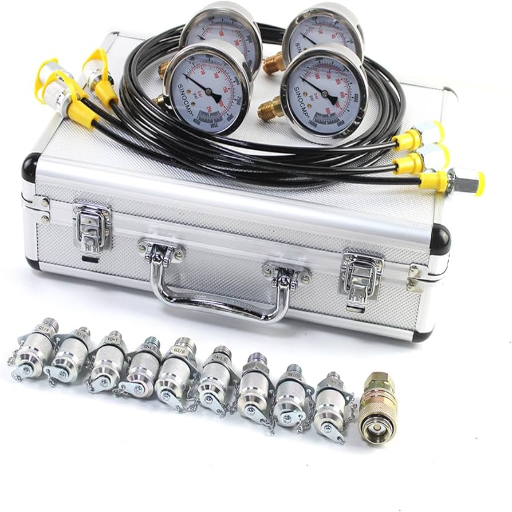
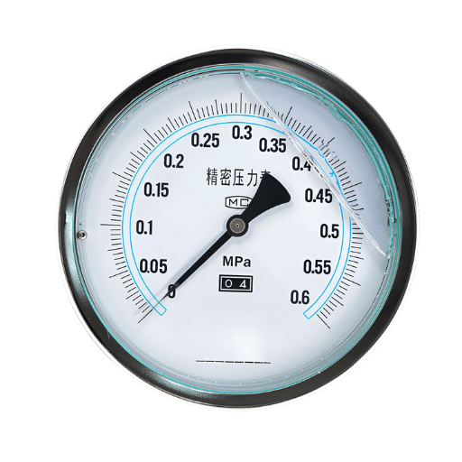
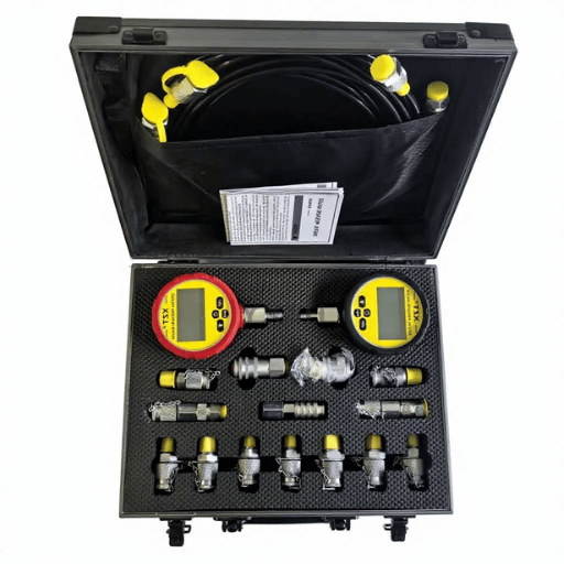
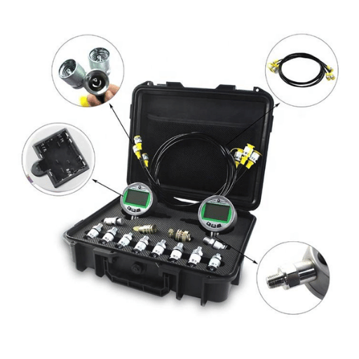
When selecting a pressure gauge, pick one with a listing at least double the maximum system pressure to stay safely in the middle third of the dial. A gauge rated for 6,000 PSI on a 3,000 PSI system keeps readings in the accurate center third of the scale. For connection to test point fittings, use quick-disconnect couplings that match the test port thread — most industrial systems use M16×2 or 7/16-20 UNF. 💡 Pro Tip Our team at Ikin Fluid recommends keeping a dedicated test kit with gauges, hoses, and adapters pre-assembled for your most common hydraulic equipment. Having the right couplings ready eliminates the delay of hunting for adapters when a machine goes down.
Step-by-Step Hydraulic System Troubleshooting with Test Points
This eight-step process, adapted from the methodology recommended by Maintenance World’s hydraulic diagnostics guide, uses test points for diagnosing and fixing faults quickly. Follow the steps in order — skipping ahead often leads to wrong conclusions.
- Know the system. Review the hydraulic schematic. Identify where the pump, relief valve, directional control valve, cylinders, motor, and reservoir connect. Mark all test point locations on the diagram before touching the machine.
- Interview the operator. Ask when the malfunction first appeared, whether it is constant or intermittent, and whether any maintenance or pressure adjustments were made recently. These details narrow the inspection scope.
- Run the machine and observe. Warm the hydraulic oil to normal operating temperature (typically 100–130 °F / 38–54 °C). Operate each function — extend, retract, steer, lift — and note which ones are affected. Listen for cavitation whine at the pump inlet or banging from relief valve chatter.
- Perform visual inspections. Check the reservoir oil level and condition. Look for leakage at hose connections, cylinder seals, and fittings. Inspect hydraulic parts like the pump coupling, belt, and motor shaft for damage. Visual problems should be corrected before instrument testing.
- Check the pump output at the pump outlet test point. Connect a flow meter and pressure gauge between the pump and the control valve. Record maximum pump flow at zero load. Then increase load in 250 PSI increments up to maximum system pressure while recording flow at each step. Pump flow at max pressure should be at least 75% of flow at zero pressure — anything below that signals excessive internal wear.
- Test the relief valve. With the flow meter still in line, dead-head the system by blocking the cylinder port and reading the peak pressure. Compare this reading to the relief valve’s nameplate setting. If the valve opens early (low pressure), adjust or replace it. If it does not open at all, the system is at risk of catastrophic overpressure.
- Test directional and control valve circuits. Connect gauges at both work ports (A and B) of the directional valve. Shift the valve and measure the pressure drop across it. High pressure on one side with low pressure on the other typically means internal leakage in the valve spool or a blocked passage. Repeat for each control valve in the circuit.
- Inspect cylinders and motors. If pressure readings at the valve are normal but the actuator is still sluggish, the cylinder or hydraulic motor has internal leakage. Measure pressure at the cylinder port test points while stalling the cylinder at full stroke. Compare extend vs. retract pressure — a significant imbalance points to a worn piston seal.
💡 Pro Tip Record oil temperature alongside every pressure and flow reading. Hydraulic oil viscosity changes with temperature, which directly affects flow rates and internal leakage. Comparing readings taken at different temperatures leads to false conclusions. Our engineering team standardizes all tests at 120 °F (49 °C) ± 5 °F.
How to Read and Interpret Hydraulic Pressure Test Results
Gathering pressure data is only part of the task. Knowing what the numbers mean — and when they signal hydraulic issues — is what separates effective hydraulic troubleshooting from aimless gauge-watching. Use the table below as a reference when diagnosing readings taken at your test points.
| Test Location | Normal Reading | Abnormal Reading | Probable Cause |
|---|---|---|---|
| Pump outlet | Rises smoothly to relief setting | Stays at low pressure under load | Worn pump; pump inlet restriction; low fluid levels |
| Relief valve | Opens at nameplate setting (±5%) | Opens 200+ PSI below setting | Worn poppet or seat; contamination under seat; wrong spring |
| Control valve work port | Matches system pressure when actuated | Significant pressure drop (>15%) | Internal leakage past spool; clogged passage |
| Cylinder port | Holds steady at stall | Gradually drops over 30 seconds | Worn piston seal; scored cylinder bore |
| Return line | Low back-pressure (typically <50 PSI) | Elevated pressure (>100 PSI) | Clogged return filter; collapsed hose; restricted cooler |
ISO 4413:2010 specifies that all hydraulic system components must withstand at least the maximum working pressure, and that loss of pressure or a critical drop shall not expose persons to a hazard. When your readings fall outside normal ranges, treat them as early warnings — not excuses to keep running the machine. ⚠️ Important Never adjust pressure settings above the manufacturer’s rated maximum for the weakest component in the circuit. Setting the relief valve higher to compensate for a worn pump creates a blowout risk. Always diagnose the root cause of hydraulic pressure problems rather than masking them.
Preventing Hydraulic System Failures with Routine Test Point Monitoring
The most inexpensive hydraulic repair is the one you don’t have to make. Regular pressure oversight throughout the system via dedicated test points can identify deterioration early before it develops into a major malfunction, unplanned downtime, and costly emergency repairs that average 150-200% more than scheduled maintenance.
Data from Reliabilityweb shows that contamination is the leading cause of hydraulic equipment failure, proving that scheduled fluid quality analysis and periodic pressure checks can extend hydraulic system life by 40% or more.
- ✔ Daily: Check reservoir oil level and visual condition (color, foam, water). Inspect for external leakage at hose fittings and cylinder seals.
- ✔ Every week, monitor system pressure at the pump outlet test point during normal operating conditions. Compare to the previous week’s reading.
- ✔ Monthly: Perform a full pressure test at all test points. Check the relief valve setting, including pump and relief valve interaction under load. Measure pressure and flow rate at the pump outlet under load.
- ✔ Quarterly: Send hydraulic oil for laboratory contamination analysis (particle count per ISO 4406, water content, acid number). Replace filters regardless of differential pressure gauge reading.
- ✔ Once a year, perform a full test stand diagnostic — including pump efficiency test, cylinder drift test, and valve response timing. Document all readings as a baseline for next year.
Each monitoring interval costs far less than the downtime it prevents. A quarterly fluid analysis runs around $50–$75 per sample. Compare that to a single unplanned pump replacement at $3,000–$8,000 plus lost production hours.
Where to Install Hydraulic Test Points for Maximum Diagnostic Coverage
Strategic placement of test points determines how much of the circuit you can diagnose without breaking into the line. In our experience working with complex hydraulic systems across mobile equipment such as excavator fleets, manufacturing presses, and marine applications, the following six locations cover the vast majority of troubleshooting scenarios.
- Pump discharge line to the hydraulic control block — Captures pump output pressure and flow. The single most important test location in any hydraulic circuit.
- Pump inlet (suction) line — Detects cavitation caused by restricted suction hose, inlet filter clog, or low fluid levels in the reservoir.
- Relief valve outlet — Verifies that the pressure relief valve opens at its rated setting and seats properly when pressure drops.
- Directional control valve work ports (A & B) — Isolates valve-side faults from actuator-side faults. Install test points on both sides of the valve for differential pressure measurement.
- Cylinder and motor ports — Measures working pressure at the actuator. Reveals internal leakage in pistons, seals, and motor case drains.
- Return line (before the filter) — Elevated back-pressure here signals a clogged return filter, collapsed hose, or restricted cooler.
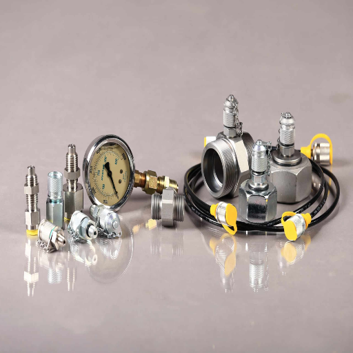
When specifying hydraulic test point fittings, match the thread type to your system standard (BSP, NPT, or metric), and select a working pressure rating that exceeds your maximum system pressure by at least 25%. Cone seal designs offer zero-leak performance under vibration — a critical factor on mobile hydraulic equipment where thread loosening is common. For expert hydraulic solutions tailored to your application, contact the Ikin Fluid engineering team. 💡 Pro Tip Label every test point with its circuit designation (P1 for pump, V1A/V1B for valve ports, C1E/C1R for cylinder extend/retract). This saves minutes on every service call — especially when multiple technicians work on the same machine. Our team uses color-coded dust caps for instant visual identification.
Frequently Asked Questions
Q: What is the function of a test point in a hydraulic system?
View Answer A hydraulic test point is a small port placed in the hydraulic line that allows a technician to connect a pressure gauge or flow meter without breaking into the circuit. It provides sealed, zero-leak access for measuring pressure, flow, and temperature at pump outlets, valve work ports, cylinder lines, and return filters.
Q: How do you diagnose hydraulic system issues?
View Answer Begin by examining the hydraulic schematic and questioning the operator – when did the issue begin, is it sporadic or persistent, were any adjustments performed? Next, operate the machine and note: sluggish motion, abnormal noise, overheating, and external leakage each lead in different diagnostic directions. Conduct a visual inspection of hose connections, reservoir level, and oil clarity. Next, attach a pressure gauge at the pump outlet test point and operate downstream, recording pump output, relief valve opening pressure, directional valve pressure drops, and cylinder stall pressure at each test point. Comparing these values against the item’s rated criteria will identify the defective component. Log oil temperature simultaneously with each measurement – viscosity is temperature-dependent, and comparing readings at different heats can give invalid results.
Q: How do I check for hydraulic pressure problems?
View Answer Hook up a precision pressure gauge at the pump outlet test point. Run the underperforming function at normal working temperature and observe the gauge. If pressure remains below the relief valve setting, move the gauge downstream – directional valve, then cylinder ports – to locate where the pressure drop occurs.
Q: What are the most common causes of hydraulic system failures?
View Answer The top five issues causing hydraulic failures are: fluid contamination (blamed for roughly 75% of all failures), internal leakage from worn seals and components, overheating from inadequate cooling or long duty cycles, aeration (air getting into the system through loose fittings or low fluid levels), and wrong pressure settings on relief or counterbalance valves. Fluid analysis and testing hydraulic pressure through test points regularly can identify most of these fluid problems prior to a mechanical failure.
Q: How can I prevent hydraulic failures?
View Answer Prevent hydraulic failures through a scheduled maintenance program that includes daily visual inspections for leaks and oil level, weekly baseline pressure readings at pump test points, monthly full-circuit pressure tests, and quarterly laboratory fluid analysis. Replace filters on schedule rather than waiting for bypass indicators. Keep the reservoir sealed to minimize contamination ingress, and always use the correct hydraulic oil grade specified by the equipment manufacturer.
Q: What tools do I need for hydraulic pressure testing?
View Answer A typical hydraulic pressure testing kit: a good-calibration pressure gauge rated for at least 2X your maximum system pressure, quick-disconnect couplings rated for thread sizes on your test points, 3ft high pressure high hose, and infrared oil temperature measurement. For more thorough diagnostics, add a portable flow meter to measure pump in GPM and a hydraulic analyzer that logs pressure, flow, and temperature.
Ready to Add Test Points to Your Hydraulic System?
Ikin Fluid manufactures precision hydraulic test point fittings with a patented cone seal design, 100% leakage-tested before shipping. BSP, NPT, and metric threads available. Small MOQ accepted. Browse Hydraulic Test Points →
About This Guide
This hydraulic troubleshooting guide was written by the Ikin Fluid engineering team — a group with over a decade of experience manufacturing hydraulic test point fittings and pressure gauge connectors for OEMs including Eaton, Parker, Hawe Hydraulic, and Sany. The diagnostic procedures described here reflect methods we use in our own testing lab and have validated with customers operating construction, marine, and industrial press hydraulic systems across 30+ countries.
References & Sources
- The True Cost of Downtime 2024 — Siemens / Senseye Predictive Maintenance Report
- Reducing the Effects of Contamination on Hydraulic Fluids and Systems — Noria Corporation / Machinery Lubrication
- Hydraulic Testing & Diagnostics: 7 Steps — Maintenance World
- ISO 4413:2010 — Hydraulic Fluid Power: General Rules and Safety Requirements — International Organization for Standardization
- Maintenance of Hydraulic Systems — Reliabilityweb.com
- 29 CFR 1910.147 — Control of Hazardous Energy (Lockout/Tagout) — U.S. Department of Labor / OSHA