How to Measure Hydraulic System Pressure: A Field-Tested Guide for Technicians
Learning how to read hydraulic system pressure is one of the most critical diagnostics a maintenance technician can learn. Whether you are taking a pressure reading on a lazy excavator arm, or verifying an actuator after a new pump installation, knowing exactly how a hydraulic system operates under pressure tells you what is going on inside – and what fails next.
This guide walks through the entire setup process: choosing a pressure gauge, attaching it to a hydraulic test point, measuring pressure, troubleshooting pressure problems. All procedures here emulate the methods used inside industrial maintenance workshops supporting construction, manufacturing, automotive, and mobile equipment use.
What Is Hydraulic Pressure and Why Does It Matter?
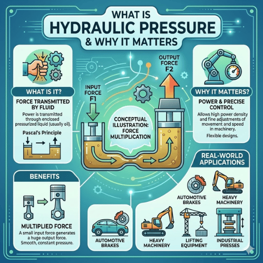
Hydraulic pressure is the force exerted upon a confined fluid per unit of surface area. It is measured in pounds per square inch (psi) or bar, and it adheres to a law first written by Blaise Pascal in 1653. According to NASA’s Glenn Research Center, Pascal’s law states that pressure applied to a confined fluid is transmitted equally throughout all parts of the fluid. Pascal’s formula is simple: P = F / A — to calculate pressure, divide force by area.
We call this phenomenon hydraulics. A small pump can transmit enormous force through hoses and valves to a larger cylinder or actuator for optimal performance. That mechanical advantage drives hydraulic machinery across nearly every heavy industry on the planet. 2,000–5,000 psi Construction Equipment 3,000–8,000 psi Aerospace Hydraulics 2,000–3,000 psi Agricultural Systems 5,000–10,000 psi Industrial Presses
Those numbers are not filler. OSHA’s Hazard Information Bulletin reports on a hydraulics-inspired accident where a hydraulic system was modified from 3,000 psi to 5,000 psi without upgrading the hoses — the coupling failed, igniting a fireball. Petroleum-based hydraulic fluid has a flash point between 300°F and 600°F. Measuring system pressure and controlling it is not just a maintenance concern. It is a safety concern.
Research studies featured in the U.S. National Library of Medicine review of fluid injection injuries: hydraulic fluid escaping through pinhole leaks at high pressures results in amputation rates of 16% to 48%. Just 100 psi can puncture a human body.
Essential Tools for Measuring Hydraulic Pressure
Prior to connecting a pressure gauge to a hydraulic system, it is essential that this equipment is available, and appropriate choice is made. Selecting the wrong gauge for a given circuit does not just produce inaccurate data for calculating pressure — it can rupture under pressure and injure the operator. Here is what field technicians actually use for their pressure diagnostics, combined with specifications that matter.
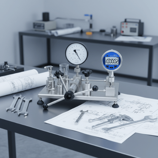
Pressure Gauges: Analog vs. Digital vs. Transducers
| Feature | Analog (Bourdon Tube) | Digital Gauge | Pressure Transducer |
|---|---|---|---|
| Accuracy | ±0.25% to ±3% FS | ±0.025% to ±1% FS | ±0.05% to ±0.5% FS |
| Response Time | 0.5–1 second | Milliseconds | Milliseconds |
| Vibration Resistance | Low (spring fatigue) | High | High |
| Data Logging | No | Yes (most models) | Yes (with controller) |
| Best For | Quick visual checks | Diagnostics & calibration | Continuous monitoring |
| Typical Price Range | $15–$80 | $80–$500 | $150–$2,000+ |
ASME B40.100-2022 specifies accuracy grades for pressure gauges. Grade 3A gauges (±0.25% of span) are used for calibration. For field work, Grade A (±1% mid-range) is usually sufficient. For diagnostic accuracy, choose Grade 2A or better.
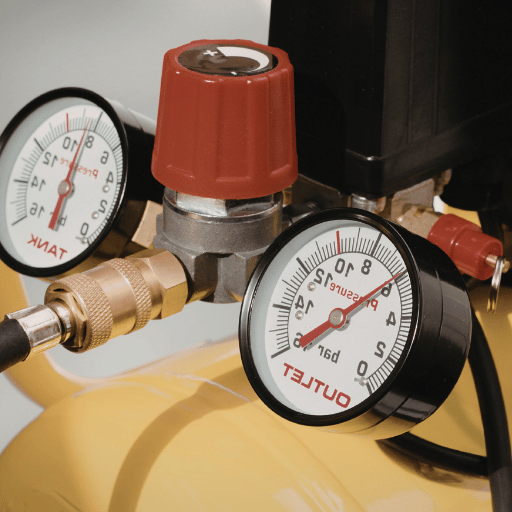
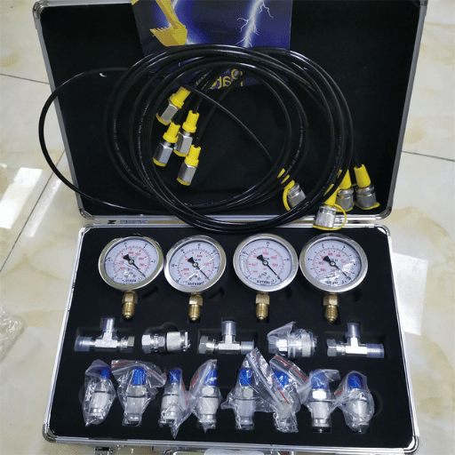
Hydraulic Test Points and Connection Hardware
A pressure gauge is only as good as the connection you make to the circuit. This is the purpose of hydraulic test points. These small threaded fittings are mounted permanently in critical circuit points on a hydraulic system, generally at the pump outlet, prior to and following valves, and on cylinder ports. They are designed so a mechanic can hook up a pressure gauge or transducer without disconnecting any hose or pipe.
Today using a spring-loaded poppet valve design is standard for test point connectors. The port remains sealed until a male hose assembly is threaded in, which depresses the poppet and uncovers a flow path to the gauge. As soon as the hose is removed the poppet reseats automatically preventing fluid loss and air ingestion. DN2 and DN4 microbore test hoses with burst ratings over 15,000 psi are used to connect gauges to test points. 💡 Pro Tip Based on our over 3,000 hydraulic system integrations experience around the world, the biggest field problem we encounter is not gauge accuracy, it is the inability of mechanics to connect a gauge in a timely manner. Pre-installed test point fittings cut diagnostic connection time from 15–20 minutes (with pipe fittings) to less than 30 seconds.
Always select a pressure gauge rated for at least 1.5x your maximum expected system pressure. This keeps your normal operating readings in the middle third of the gauge’s range — the zone where Bourdon tube gauges display the highest accuracy.
Step-by-Step: How to Measure Hydraulic System Pressure
Hydraulic pressure testing follows a consistent procedure whether you are working on a mobile excavator, an industrial press, or a CNC machine tool. Steps below reflect standard practice recommended by Ohio State University Extension and aligned with ISO 4413:2010 safety requirements for hydraulic fluid power systems. ⚠️ Safety FirstOSHA Standard 1926.302 states: “The manufacturer’s safe operating pressures for hoses, valves, pipes, filters, and other fittings shall not be exceeded.” Never connect a gauge rated below the circuit’s maximum possible pressure. Never search for leaks with your hands — use cardboard or paper instead.
- Power down the system and relieve all stored pressure. Shut off the hydraulic pump. Retract all lifted implements to the ground. Cycle all control levers to each position several times in order to bleed residual pressure from the cylinder chambers and accumulators.
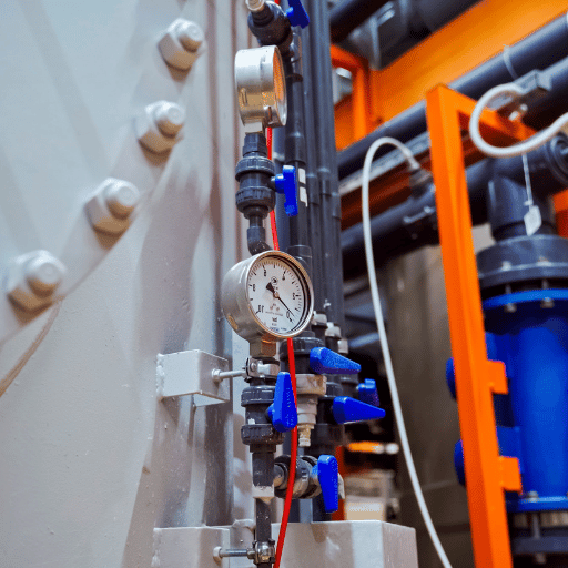
- Locate the IKIN hydraulic test point connectors or gauge ports on the circuit you need to test. Common locations are the pump outlet (system pressure), relief valve port (maximum pressure), and cylinder ports (load-holding pressure).
- Select a gauge rated for at least 1.5 times the maximum pressure you anticipate. Ensure it has been calibrated in the last 12 months. Inspect for broken glass, bent needles, or fog inside the dial — any of these indicate a damaged gauge that will produce unreliable readings.
- Hook up the gauge using a test hose. Thread a microbore test hose onto the test point. Verify the connection is finger-tight plus one-quarter turn with a wrench. Do not over-torque — this damages the poppet seal and causes leaks.
- Set pump to low idle for 3-5 minutes in order to warm the hydraulic fluid. Viscosity varies with temperature, which directly impacts pressure readings. Cold fluid causes higher-than-normal readings due to excess flow resistance.
- Bring the system to normal operating pressure. Operate the circuit you are testing—extend a cylinder, rotate a motor, engage a valve—and watch the gauge. Record both the steady-state pressure and any pressure spikes during load changes.
- Compare to the manufacturers specs. Every hydraulic cylinder has a rated working pressure stamped on the nameplate or printed in the service manual. Your gauge reading should be within the specified range. Readings more than 10% above or below the rated pressure are a sign of trouble.
- Shut down the pump and vent system pressure again before disconnecting the gauge. Record your readings, the fluid temperature, and the date. This data becomes the baseline for future comparisons.
💡 Common Mistake to Avoid Not bleeding trapped air from the test hose before reading the gauge. Air trapped in the line compresses under pressure and causes artificially low or irregular readings. After connecting the gauge, crack the bleed screw (if installed) or briefly loosen the hose fitting at the gauge until the fluid appears—and retighten.
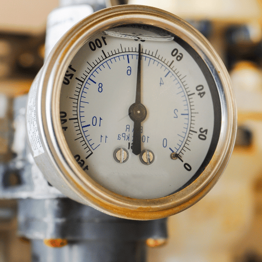
How to Read and Interpret Pressure Gauge Results
A pressure gauge measures the pressure at one point in the hydraulic system. But that single figure indicates different things depending on when and where you take it. Below is a table of common readings and what they tell you about your hydraulic circuit.
| Gauge Reading | Possible Cause | Recommended Action |
|---|---|---|
| Pressure within rated spec | Normal operation | Log reading; retest in 30 days |
| Pressure 10–20% below rated | Worn pump, internal leak past cylinder seals, relief valve set too low | Isolate pump from circuit and retest; check cylinder drift under load |
| No pressure / gauge reads zero | Pump failure, broken coupling, reservoir fluid level critically low | Check pump rotation, coupling integrity, and fluid level immediately |
| Pressure above rated spec | Relief valve stuck closed, blocked return line, thermal expansion | Shut down immediately; do not operate above rated pressure |
| Rapid oscillation / needle jumping | Air in the system (aeration), cavitation at pump inlet, failing piston | Check suction line for air ingestion; verify fluid level and filter condition |
| Slow pressure decay under load | Internal bypass past valve spool, cylinder seal wear, check valve failure | Perform a cylinder drift test; replace seals if drift exceeds spec |
Cavitation and aeration are two different pressure problems that technicians often confuse. Cavitation occurs when the absolute pressure in a fluid drops below its vapor pressure—the fluid actually vaporizes internally, creating a high-pitched whine and damaging pump parts. Aeration happens when air enters the system through a leak on the suction side, creating irregular pressure pulses and a low-rumble sound. Both result in erratic gauge readings, but fixing the problem is different. 💡 Pro Tip When a gauge needle fluctuates quickly, place a snubber (pulsation dampener) in line between the test point and gauge. A snubber limits the flow path to the gauge, preventing pressure spikes without affecting the average reading. This protects the gauge and allows you to get an accurate measure of the actual system pressure.
Pressure Testing Procedures for Specific Hydraulic Components
Different hydraulic components use different pressure test procedures. The procedures below are for the four components most often tested by technicians.
Hydraulic Cylinder Pressure Test
ISO 10100:2020 recommends that hydraulic cylinders be proof-tested at 1.5 times their rated working pressure. Connect a gauge to the cylinder service port, exert pressure to the rated pressure, close the valve, and watch the gauge for two minutes. Any pressure drop indicates a bypass between the cylinder’s internal piston seal leak. A hydraulic cylinder pressure test should include extending and retracting the rod under load to check for uneven pressure across the stroke.
Hydraulic Pump Testing
To evaluate pump efficiency, install a gage at the pump outlet and a flow meter downstream to measure flow rate. Run the pump at rated speed and incrementally increase the load by adjusting a relief valve. Normal pump operation at rated speed, with incremental load increases, will yield rated flow within 5% until the relief pressure is reached. Flow rate loss greater than 10% at rated pressure signifies internal part (gears, vanes, pistons) wear within tolerance and in need of replacement.
Relief Valve Testing
Relief valves are the pressure limit of every hydraulic circuit. To test one install a gage between pump and relief valve. Incrementally increase system pressure by restricting flow downstream (dead-heading the circuit). Watch the gage rise steadily until the relief valve opens; the relieving pressure should equal the valve’s rated set point within 3%. Record the reseat pressure as well; the pressure point at which the valve reseats after the overpressure event. Typical blowdown is 4% to 7%.
Accumulator Pre-Charge Testing
Bladder and piston accumulators regulate energy storage by maintaining pressurized hydraulic fluid against a gas charge — typically dry nitrogen, never air or oxygen (unlike pneumatic systems that use compressed air directly). Fluid Power Journal recommends pre-charging bladder accumulators to 80% of the system minimum operating pressure, with some variation by application. Piston accumulators’ pre-charge should be approximately 100 psi less than the system minimum operating pressure. Pre-charging should be done at operating temperature, since gas pressure is highly temperature-sensitive.
Troubleshooting Common Hydraulic Pressure Problems
If any of the related pressure readings do not fall within reasonable limits, chances are good one of the following five root causes created the problem. Here are the ones most frequently encountered by our team with field service.Top 5 Hydraulic Pressure Problems — Ranked by Frequency
- Contaminated hydraulic fluid. Machinery Lubrication estimates 75% of hydraulic system failures result from contaminated or degraded fluid. 5-micron particles can cause significant valve scoring and internal leaks, causing pressure losses that prevent required pressure levels. New fluid can contain over 500,000 particles at this threshold per 100 ml.
- Worn piston seals and valve spool clearances allow pressurized fluid to bypass, reducing pressure at the actuator. Under load, this produces cylinder drift. Cylinder drift under load is the classic symptom of internal seal wear.
- Relief valves that are set too low will bleed pressure from the system before the working rating is reached. A valve stuck open eliminates system pressure entirely. Always verify relief valve cracking pressure during routine testing.
- Aerated fluid. Loose suction fittings, low reservoir levels, and/or damaged pump shaft seals can all introduce air into the fluid. This produces compressible pockets that cause erratic pressure drops, potential leaks, and foaming.
- According to NIOSH Publication 93-105, injuries and fatalities caused by metal-reinforced hydraulic hose failures. Corrosion on fittings, aged hoses, and improperly torqued connections lead to both leaks and catastrophic ruptures.
Fluid cleanliness is indicated via the ISO 4406 code system, which is based on counts per ml for particles 4, 6, and 14 microns in size. Typical industrial grade hydraulic system should be no worse than ISO 18/16/13. High pressure servo valve systems require ISO 15/13/10. If your pressure readings are dropping and the fluid looks dark or smells burnt then immediately send in a sample for particle count before changing anything.
“In our experience serving 3,000+ hydraulic system integrators across the globe, the single most cost-effective diagnostic investment is a permanently installed test point network. Technicians who can measure pressure at every critical junction catch contamination damage weeks before it causes a shutdown.”
— IKIN Fluid Technical Team
McKinsey research found that predictive maintenance — triggered by regular pressure and flow monitoring — reduces maintenance costs by 10–40% and cuts unplanned outages by up to 50%. Modern control systems with integrated pressure transducers make this level of monitoring practical even on older equipment.
Maintaining Pressure Measurement Accuracy Over Time
Because a pressure gauge is a precision instrument, over time it is subject to drift. This is especially true of analog gauges with a mechanical Bourdon tubes that are subject to spring fatigue and impact damage. Here is how to keep your readings reliable.
| Maintenance Task | Frequency | Standard |
|---|---|---|
| Full calibration (5-point test: 0%, 25%, 50%, 75%, 100%) | Every 12 months | ASME B40.100 |
| Calibration — harsh environment (above 80°C or vibration >15g) | Every 6 months | ASME B40.100 |
| Visual inspection (glass, needle, dial fogging) | Before each use | Best practice |
| Accumulator hydrostatic retest | Every 5 years | ISO 4413 |
Temperature has a major effect on gauge accuracy. For every 18°F (10°C) shift from the calibrated temperature, expect up to ±0.4% full-scale error. If you calibrate a gauge in an air-conditioned lab at 72°F and then use it on a hydraulic system running at 150°F, the reading could be off by nearly 2%. Diaphragm seal gauges can be isolated from hot fluid or the gauges can be calibrated at temperature.
Maintain gauges in their original box at 40–85°F with humidity below 85%. For extended storage, seal them in plastic bags with desiccant packs. Liquid filled gauges should always be stored upright; during cold weather, freezing temperatures can expand the fill fluid and crack the lens. Reference calibration equipment should be three times as accurate as the gauge being calibrated, per ISA calibration guidelines.
Frequently Asked Questions
Q: How do you measure pressure in a hydraulic system?
View Answer In order to take a pressure reading in a hydraulic system, you must have a pressure gauge that is calibrated at a test point along the circuit you seek to measure. Shut down the system and relieve stored pressure first. Connect the gauge using a microbore test hose, restart the pump, warm the fluid to operating temperature, and actuate the circuit under normal load. Record the steady-state reading and compare it against the manufacturer’s rated pressure specification.
Q: Is hydraulic pressure measured in psi?
View Answer Absolutely. Psi (pounds per square inch) is the exclusive currency in the United States. Bar is a metric measure, the equivalent of about 14.5psi.
Q: How do you perform a hydraulic pressure test?
View Answer A hydraulic pressure test is conducted by attaching a pressure gauge to the system at the component to be tested. The circuit is then activated on full load and the pressure reading is noted. How this is done is: firstly, relieve all stored pressure, next select a gauge that is rated at least 1.5 times the highest anticipated reading, then connect it directly to a gauge port or a test point via a microbore test hose. Start the pump and bring the fluid up to its operating temperature, then activate the circuit you are testing while noting the steady state pressure reading, finally compare it to the manufacturers rated pressure specification. Always follow OSHA safety precautions — wear eye protection and never use your hands to locate leaks.
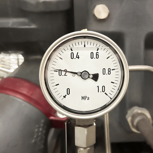
Q: What is a hydraulic pressure gauge?
View Answer A hydraulic pressure gauge is an instrument that displays the pressure of hydraulic fluid in a system. The type that is most familiar to people is a Bourdon tube, which is a curved metal tube. As the fluid pressure increases, the tube uncurls itself slightly, pushing a pointer across a dial that has pressure values calibrated on it. More modern digital pressure gauges employ electronic sensors (normally piezoresistive transducers) and digital LCD readout displays and tend to be more accurate and capable of data-logging.
Q: What causes pressure loss in a hydraulic system?
View Answer Pressure loss in a hydraulic system tends to be caused by internal leaks (worn out seals, scored valve spools, bypassing pistons), external leaks (failure of the hoses or loose fittings), a failed or worn out pump, relief valve that is set too low, contaminated fluid that accelerates component wear and corrosion. Less obvious causes include aeration (i.e., the presence of air in the fluid), high fluid viscosity owing to low temperatures and extreme drops in pressure across clogged filters in the filtration circuit.
Q: How often should hydraulic pressure gauges be calibrated?
View Answer There is no reason why most hydraulic pressure gauges should not be calibrated at least once every year – following the 5-point test procedure specified in ASME B40.100 – where readings are checked at 0%, 25%, 50%, 75%, and 100% of full capacity against reference equipment that is at least 3x more accurate than the gauge being tested. If fluid is used in high temperatures or in a harsh environments where there are higher levels of vibration, then calibration should be more frequent (minimum every 6 months). Gauges that are used as a safeguard in safety-critical systems that could harm personnel should be calibrated even more frequently according to safety guidelines on-site. Always keep a calibration log so the details of every calibration test can be recorded and accessed easily.
Need Reliable Hydraulic Test Points for Your Systems?
IKIN Fluid manufactures hydraulic test points, pressure gauge connectors, and microbore hoses used by Parker, Eaton, and 3,000+ integrators worldwide. SGS-certified quality. 100% leakage-tested before shipping. Explore IKIN Test Point Solutions →
About This Guide
IKIN Fluid has manufactured hydraulic test point connectors and pressure gauge fittings since 2009. The measurement procedures and troubleshooting approaches in this article reflect field feedback collected from our network of over 3,000 hydraulic system integrators and OEM partners — including Hawe Hydraulic, Bucher, and Sany. All safety data and standards referenced are from publicly available government and industry sources cited in the References section below.
References & Sources
- Pascal’s Principle — NASA Glenn Research Center
- Hazard Information Bulletin: Hydraulic System Modifications — U.S. Department of Labor (OSHA)
- Injection Injuries: Seemingly Minor Injuries with Major Consequences — U.S. National Library of Medicine (PMC)
- ASME B40.100-2022: Pressure Gauges and Gauge Attachments — American National Standards Institute (ANSI)
- Safe Use of Hydraulic Systems (AEX-591.25) — Ohio State University Extension
- 29 CFR 1926.302: Power-Operated Hand Tools — U.S. Department of Labor (OSHA)
- ISO 4413:2010 — Hydraulic Fluid Power Safety Requirements — International Organization for Standardization
- ISO 10100:2020 — Hydraulic Cylinders Acceptance Tests — International Organization for Standardization
- Gas-Charged Hydraulic Accumulators — Fluid Power Journal
- Reducing the Effects of Contamination on Hydraulic Fluids — Machinery Lubrication
- Publication 93-105: Preventing Injuries from Metal-Reinforced Hydraulic Hoses — NIOSH (CDC)
- A Smarter Way to Digitize Maintenance and Reliability — McKinsey & Company
- Basics of Calibrating Pressure Transmitters — International Society of Automation (ISA)