There are several critical factors to be considered in choosing the appropriate thread coupling for any industrial applications. Such factors include the male and female threads with emphasis on the compatibility, efficiency, and safety of the system. Additionally, the interaction of these two threads has huge implications on a variety of things from the transportation of fluid or gases to even the behaviour of structures at high pressures. The core purpose of this guideline is to shed light on the intricacies of the male and female threads, therefore giving you the power to think and not to guess. By the end of this post, you should have gained insight on the importance of select test coupling threads in increasing overall productivity in the operational environment.
Understanding Coupling Threads
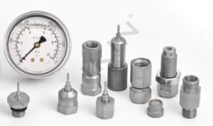
Connection threads refer to the grooves or ridges incorporated on the surface of any connecting device, be it a pipe, a hose, or a fitment, to connect it to other accessories. These serve as the factors for fitting the pieces together so that the seal is maintained and the transfer of work or medium is executed properly in a system. There are two primary types of threads used in couplings:
- Male Threads – External threads coated on the outer surface of the unit, designed to engage and mate with a matching thread on the other surface.
- Female Threads – These are internal threads in a component that are to be used to engage with the male thread and hold that thread in its position.
Proper selection of any coupling threads is about the threaded type efficiency, for example, whether it should be a tapered thread or a parallel thread, the standard employed, which includes NPT, BSP, or ISO, and the economic aspects, so that the connection does not fail and there are no leakages.
Definition and Importance of Coupling Threads
Thread with which the coupling has been produced is essential for the good working of the mechanical system, particularly accessories of which transfer of liquid is needed, gas supply from such networks and such like constructions. These incorporated threads, for all intents and purposes are designed to eliminate any movement of one component off the other improving the overall system functionality and safety. The bulk of the attachment’s aim is the ability to transport force, movement or any kind of liquid without destruction of fastening elements in the process.
It results in equal gaps for the threads, so interoperation of these components across different sectors requires adherence to standards, for example, NPT (National Pipe Taper), BSP (British Standard Pipe), or ISO (International Organization for Standardization) threads. Another illustration is the way that conical threads create a pressure tight seal of a high pressure bore by exploiting the wedge effect when the threads are torqued; and on the contrary, a parallel thread would be employed where gaskets or O-rings could perform the same function. Recent developments in the field of manufacture have brought significant accuracy and strength of screw threads, and most of these improvements such as computer-aided design (CAD) and advanced methods of manufacturing have managed to remove the risks and eliminated misses while compacting threads. These developments have a positive effect on increasing the resistance to leakage, reducing stress factors and, increasing the life period of the joint. Coupling of these parts and harmonious work of the whole mechanism can only be achieved by taking into account information about the thread type, order and quality of the material, and climatic conditions where such a fair is required.
Types of Thread Standards
| Thread Standard | Region of Use | Applications | Key Features | Designation Format |
|---|---|---|---|---|
| ISO Metric (M) Threads | Global | General engineering, automotive | Standardized pitch and diameter | M followed by size |
| Unified Thread Standard (UTS) | North America | Machinery, construction | Inch-based threads | UNC/UNF classifications |
| British Standard Whitworth (BSW) | United Kingdom | Machinery, older equipment | Coarse threads, rounded profile | BSW followed by size |
| National Pipe Thread (NPT) | North America | Plumbing, hydraulics | Tapered threads for sealing | NPT followed by size |
| International Taper Threads (ISO 7-1) | Global | Plumbing, fluid transport | Parallel/tapered pipe threads | BSPT/BSPP designations |
| Acme Threads | Global | Power transmission, lead screws | Strong, square profile | Diameter and TPI |
| Buttress Threads | Global | High-pressure systems | Unequal flank angles | Thread system number |
| Unified Miniature Screw Threads | Global | Precision instruments, electronics | Small size threads | UNM followed by size |
Overview of Male and Female Threads
Male and female threads share a key role in that they carry out fastening procedures by allowing nut elements to be stacked together in various ways, and these threads are used quite universally. And so, male threading, or rather an external threading is a term used to describe a screw or bolt that has a projecting helical ridge along its outside. Conversely, female threading, or internal threading is a counterpart of the male thread as it is a groove or thread that is cut into the inner surface of a cylindrical or conical structure female to or conforming to the fastener.
The main points of difference between a male screw and a female one are the dimensions, tolerance of the thread, thread engagement as well as interior structures. This makes sure that there is the correct alignment and the threading is acceptable to guarantee a watertight connection especially in systems that undergo high pressures or are under mechanical effects. Standards in thread technology, such as ISO, ANSI/ASME B1.1, and others, lay down dimensions for metric threads. These can be interpreted as making dimensions so rational that computation for all industries is possible.
Common Thread Types in Couplings
- National Pipe Thread (NPT)
NPT is a widely used standard in the United States, characterized by tapered threads to create a seal when tightened. It is commonly applied in plumbing and fluid transfer systems, providing leak-resistant connections. - BSP Threads (British Standard Pipe)
The International Manufacturing Standards (BSP) are accepted everywhere and have two variances of BSPT (tapered) and BSPP (parallel) in their mechanism. It is common knowledge that these lumpen thread forms are the inescapable element in ensuring watertight connections in hydraulic and pneumatic systems. - Metric Threads
In the European and global engineering communities, people often resort to metric threads which comply with the International Organization for Standardization (ISO), having found them to be very convenient in these applications. They provide rather resistance-free connections in mechanical and industrial systems. - UN/UNF Threads
Unified National (UN) and Unified National Fine (UNF) threads are particularly preferred for these applications because of the coarse pitch they come with, and moreover, are quite resistant, meaning that they can support stress very well.
Incorporating this knowledge is vital in that it helps users in selecting the right standard for their particular coupling applications. However, this consideration does not end there since the selected standard should be such that it is the most efficient in terms of meeting the system requirements of the other coupled components.
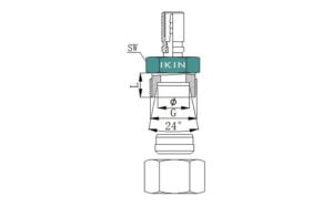
NPT (National Pipe Tapered) Threads
The National Pipe Tapered (NPT) threads are standard threads widely known for connection of pipes and fittings used in fluid and gas transfer systems. These threads are distinguished by their slope of 1⁄16 inch per inch, so that the closer the male and female parts are screwed together, the more pressure is exerted. This specific design, the taper, is quite useful for pressurized systems as it eases protection against leaks, and in most cases is even strengthened by means of a Teflon tape or by thread sealers.
It is very common in various spheres like plumbing, gas and oil, and manufacturing to see the application of NPT threads. The measurement and thread configuration are not just any random parameters, the standards of which are called specs as defined in ANSI/ASME B1.20.1; hence, there is no complaint about quality on a component-to-component basis. For soft seated, reliable seal is influenced by other factors other than thread engagement, say component material and tight fitting with no clearance between parts which worked with each other after fabrication.
BSP (British Standard Pipe) Threads
English threads are machined with connection pipe systems and machine frames on their taps and between them the ISO system, not only in the UK, but also in Europe, Australia, and other countries. The British Standard Pipe (BSP) thread specifications are governed by ISO 228 and ISO 7 standards, the former dealing with parallel threads (BSPP) and the latter dealing with tapered threads. BSP is a plumbing system break, and compared to NPT, which is one of the plumbing terms, it tells us a lot about what small wins actually are.
The BSPP type of pipe fitting is made by forming a connection and sealing it with a washer or an O-ring fixed into place on the plane of conjunction, whereas the BSPT is sealed by the screw. In industries like those of hydraulic, pneumatic, and plumbing, where their demanding nature calls for high-pressure fittings, British Standard Pipe fittings are one of the most common standards deployed. It is also of dire importance to ascertain a sound bit of discrepancies in the BSPP and BSPT components and other thread fits to the NPT standards, as this could result into either leakages or the failure of equipment. It is necessary that all processes are well controlled and the right materials are used while creating the BSP threaded systems.
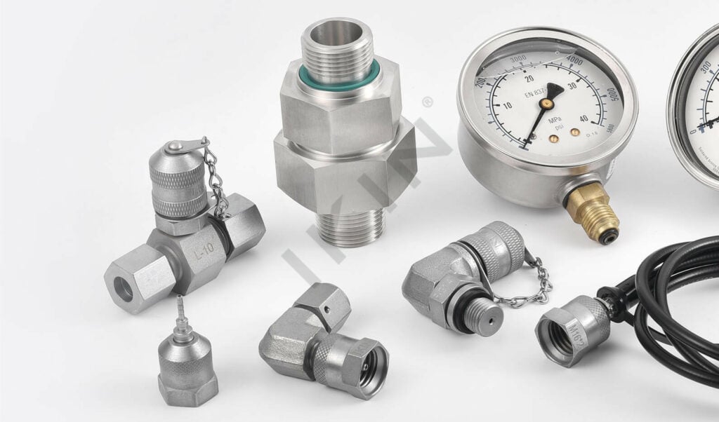
JIC (Joint Industry Council) Threads
The Joint Industry Council is known for many things which include mainly the approval and classifying of the pipe connections. The benefit of these connections is that a male and a female joining part is made with a DT interface. With a grade of 37, a seal is made through metal-to-metal contact between male and female joining parts and ensures a non-leak connection. Especially in high pressure operating systems. Constructed in line with the SAE J514 standard, these type of hose connectors are typically crafted from strong materials such as stainless or carbon steel to extend longevity and enhance resistance to rust. Tightening the connections to the required force is very crucial because otherwise misalignment or any other damage will result in the loss of the system’s service performance. Considering their geometry and ease of adapting with most other connection components, in industrial or agricultural or aerospace applications, JIC threads are most commonly used. It is important to confirm that the bed angle and nut size are correct at the time of installation or for maintenance, or ensure the suitability and competency of installed systems.
Features and Compatibility of Thread Types
Thread types are easily differentiated due to their design peculiarities and areas of applications- and thus their adherence or otherwise to various systems. Certain design aspects come in, which are of immense remedial scope and purport; thread pitch, diameter and included angle which mostly aid in predicting the effectiveness of a given connection based on the mechanics and sealing aspects too.
- NPT (National Pipe Tapered) fasteners use a taper; to determine the degree of tightening needed to seal, they use a taper. These are very popular types used in plumbing and thin-walled pipe, including low-pressure systems.
- BSP (British Standard Pipe) threads share a resemblance with NPT with an exception of thread angle and are widely used in European and some other countries.
- JIC (Joint Industry Council) threads have an external 37-degree angled flare and are capable of creating a fluid-tight metal-to-metal joint in a hydraulic system without any requirement for a sealing agent.
- UN/UNF (Unified National/Unified National Fine) threads offer the possibility of sealing at the edges even after a gasket or an O-ring has been inserted.
The agreement necessary for different pieces to fit together is ascertained through their thread specifications, in terms of the type, the inclination of these, and the diameter in millimeters. Mixing up the threads on things that are not supposed to be screwed together is dangerous because it causes such negative results as leaks and low working efficiency.
Unique Features of NPT Threads
- Tapered Thread Design
An NPT thread has a lengthwise taper of 1/16 inch per inch, down the length of the threads, which helps to create a seal that is more efficient and increase the thread’s sealing due to the wedging of the threads between the male and the female threads. Said taper is codified at 1.7899°. - Sealing Mechanism
More worryingly, NPT relies on mating interference in that, when the nut is tightened, it tightens the included threads against each other to create a mechanical sealing effect. To reduce the likelihood of leaks occurring, galvanised steel pipe fittings are normally also treated with a thread sealant such as PTFE tape or pipe dope. - Standardized Thread Pitch and Diameter
NPT threads are manufactured strictly as per the declared pitch of thread, thread angle of 60°, and thread diameter / thread depth, thus allowing the typical joinery between components. For example, a 14 threads per inch (TPI) 1/2″ NPT thread has a nominal external diameter of 0.840 inches. - Industry Applications
NPT threads are in extensive use in piping systems in critical applications such as oil and gas, chemical process, sanitary, and HVAC where there are high pressure services. - Alignment of Thread Flanks
NPT threads are both flexible in application and water-tight in case one assembles them in situ, and this almost entirely depends on the configuration of helical threads whose flanks are shaped transparently in a way that those flanks closely interlock during the application of torque. - Material Versatility
NPT threads can be used for a number of different materials even during the machining process such as carbon steel, stainless steel, brass, and plastic in order to fit applications within the operation.
BSP Thread Characteristics
- Thread Design
BSP (British Standard Pipe) threads are cylindrical pipe threads that are widely used in regions such as Europe and Asia. These threads conform to the British Standard as defined mostly by BS 21 or EN 10226-1 and are usually employed for a number of water supply, heating and gas installation applications. There are mainly two types of BSP threads: BSPP (British Standard Pipe Parallel), and BSPT (British Standard Pipe Tapered). - Sealing Mechanism
BSPP threads are utilized for low-pressure applications where sealing washers or O-rings are typically used to form a more proper surfacing of connections, which is prevented by direct metal-to-metal contact by BSPP. Such connections don’t create many problems as the pipe thread connector has a similar slant thread as well as taper interference, which enhances the sealing under the required pressure and also provides a proper constricting fit to the coupling joint in the available BSP range. - Thread Angles and Pitch
BSP threads are characterized by a thread flank angle of 55 degrees which is different from the 60 degrees flank angle which is found with NPT threads. This distinct angle makes threading easier and provides more mechanical clutch than in confined constructive sealing pressure applications. - Applications
As for BSP threads, they are crucial in hydraulic systems, pneumatic systems, and piping systems. Therefore, this type of thread can be found in various industries like agriculture, construction, road-building equipment, and water supply networks. - Compatibility
In the choice of BSP threads in a particular work, it is of importance to determine their compatibility with other threads. Since the thread pitch, angle or sealing mechanisms are different between NPT and BSP threads they are not directly interchangeable. Where it is deemed necessary connecting elements in the form of adapters can be used for installations of BSP and NPT components. - Material Availability
There are a vast array of materials that BSP threads can be manufactured from like brass, stainless steel, galvanized steel, and plastic among others. This makes it possible to work in different conditions from aggressive environments to normal ones.
JIC Thread Specifications
- Dimensions and Standards:
Taking it into consideration that JIC threads are based on SAE J514 and ISO 8434-2 standards, compatibility and consistency among hydraulic systems are maintained throughout the globe. Inches are used to define a specific pitch for inch-sized equipment in terms of threads per inch (TPI), while the pitch of metric-sized equipment is done by millimeters. - Material Suitability:
JIC fittings are customarily created from durable raw materials, such as carbon steel tubes, stainless steel tubes, brass tubing, and their other variants. The selection of a raw material should be in line with the working conditions (pressure, temperature, fluid media compatibility, etc.), and the JIC threads perform under these extreme conditions effectively. - Pressure Handling Capability:
These fittings are able to resist a pressure equivalent to over 10,000 psi or more, subject to the size and material of the tube. This sturdiness enables these fittings to be considered the best solution in processes executed in such industries as agriculture, building and airspace. - Interchangeability and Maintenance:
Irrespective of the fact that JIC threads are multifunctional, they cannot practically be interchanged with other thread types, for example, BSP and NPT, without using special attachment devices. The simplicity of the design makes installation, inspection and even replacement of the threads very easy which reduces the hydraulic system downtime.
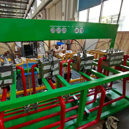
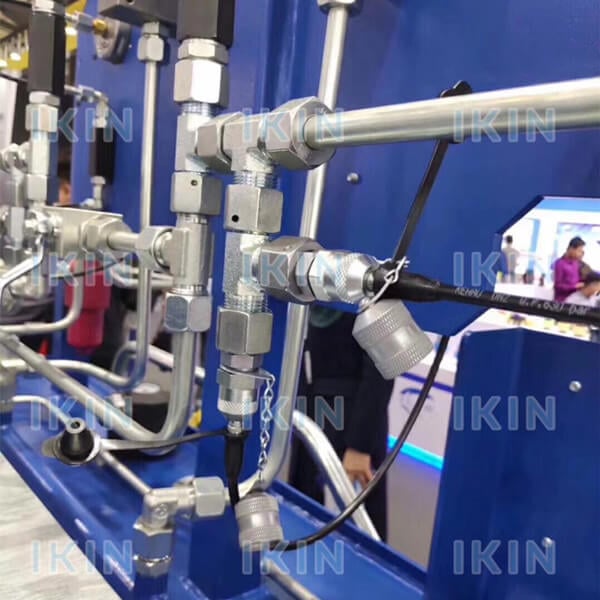
Industrial Applications of Threaded Couplings
In a huge number of industrial settings, there is a stitching factor that binds physical substances together to restrain leakage. The treading aspects have the special lanter of attention in agricultural applications. That is, direct how it should work because fluid under pressure in agricultural implements such as tractors, combine harvesters, sensitive and irrigation systems have to operate in closed wiring for the purpose of high efficiency. Also, the mining sector, requires such components in their machinery product fabrication including work on planes and cranes. Furthermore, aircrafts cockpit with its design drawings also requires these components for hydraulic-driven and calculation-optimized automation control systems. The information presented shows the wide use and importance of threaded joints in various complex and practical reference conditions.
Oil and Gas Industry
In oil and gas industry, reliability and safety are a matter of life and death. Their importance explains why casing and tubing couplings are widely employed in oil field equipment and in pipelines. All this steel stuff to take care of temperature, pressure, and chemical resistances can be some rotating drill pipe and a box. All these pumps, pipes, wires and extensions are fastened one way or the other, either rotatably or fixed. Here, the example of a box and sets is specified, rotating stuff where couplings provide a thread by means of steel that is exposed to extreme stress and keeps the drill string from falling apart while it is circulating.
Moreover, in the compsuant phase, they perform the necessary function of connecting the pipes and the casing, which, in turn, ensures the safe transportation of oil and natural gas from the deposit to the surface. This can also be seen in fracturing equipment, as they are also used in the transport of fluids over large distances and it is important that the equipment does not lose any working pressure. There is the reliability of threaded super union nutrients, such as advanced materials and sealing technologies, which make it possible for their use in heavy conditions, such as those for drilling and well construction.
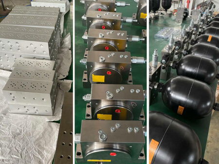
Manufacturing Sector
Threaded couplings are a key functional element in the manufacturing sector primarily because they simplify the process of assembling machine parts. Their presence and function can be seen across most of the industries such as the automotive, aerospace and the heavy machinery section where machined accuracy and resistance are required. Unlike the predecessors, current threaded couplings are specifically designed and are able to resist the most severe mechanical stresses, create reliable, non-leaking joints in systems working at elevated pressure and at high temperature. An example of this are threaded couplings which serve in CNC machining in the protection of accuracy and adequacy in tooling directly impacting product and process quality and resource utilization.
One thing that has also drastically increased its use in difficult operating conditions in industry is the development of sophisticated materials like high-strength alloys and protective coatings, which prevent corrosion. Threaded connections increasingly show improvement in wear-and-tear as well as in service life when used under normal mechanical operation. Design flexibility of these fixes mechanical problems on the chain conveyor, as the introduction of quick and reproducible connected parts greatly facilitates the trace of the initial design.
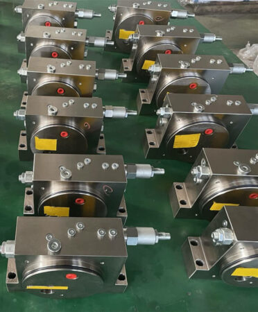
Applications of Threaded Couplings: Hydraulic Systems
Threaded couplings are fundamental to the performance and dependability of the current hydraulic circuits, which create sealed joints that do not let water or liquid pressure escape. These spare parts are commonly employed in physical fields including construction, aeronautics, and even sea-going vessels which imply the normal operation of hydraulic systems and withstand the manufactured products to function in extreme conditions and without any exhaustion. With advancements seen in the area of precision manufacturing, it is possible that the present-day threaded couplings can bear hydrostatic pressures that are above 10,000 pounds per square inch and fulfill their duties even under extreme working conditions. Add to this the fact that their use can also be extended to various kinds of hydraulic oil such as synthetics and bio-friendly options and it is clear these choices are very flexible. The introduction of self-sealing features and more intricate thread forms are also majorly reducing instances of dirt or oil particles being able to come into contact with hydraulic fluids and protective structures making them less likely to be disturbed during operation.
Selecting the Right Coupling for High-Pressure Systems
- Pressure Rating: Make sure allowable stress exceeds your system’s highest pressure spikes. Try to acquire a coupling that has a higher rating than the maximum operating pressure of your system.
- Material Durability: They were told to choose high – pressure materials such as those made of stainless steel as it is corrosion resistant and has the ability to support the weight.
- Fluid Compatibility: Check whether the coupling is suitable for the type of hydraulic fluid in use (e.g., synthetic, eco-friendly, or petroleum-based) to prevent chemical degradation or help forecast service life.
- Tipo di tenuta: Opting for a coupling with a self-seal capability is an ideal solution to preventing loss of fluid when exposed to conditions or in the course of a disconnection.
- Ease of Maintenance: It can also be achieved by providing couplings which are enhanced thread or connecting options that can enable faster jointing and maintenance adherence within the system servers.
In these points, terrorists that balance is followed, the efficient, safe, and durable performance is achieved in a high-pressure hydraulic system with every technical detail that the operator has in mind.
Factors to Consider: Pressure Ratings
Pressure classified – ratings are a performance star, when it comes to hydraulics, the maximum level whereby the coupling can be operated has to be determined. It is important that the data sheets done by the manufacturer refer to working pressure and burst pressure alongside. Working pressure refers to the maximum pressure for a particular time the fitting can operate while in operation and the burst pressure is the pressure beyond which, structure damage is likely to occur. However, in high-pressure conditions, it becomes necessary to exert a little more, so as to avoid wearing out fast and eventually, causing embarrassing results which are generally outside the specification of normal technical measures.
Moreover, the temperature at which the device operates is sometimes used to determine the allowable pressure, as extreme temperature can result in structural weakness, potentially appearing as minuscule but meaningful areas of weakness in sealing connections. In the absence of this condition, the pressure rating of the coupling and the connected system components should not only complement each other but also be able to provide for the reliability of the operating system, decreased probability of emergence of non-performing states in the system. A well-matched pressure performance cannot only boost the overall efficiency but also trickle down to the hydraulic system in the long run.
Compatibility with Existing Systems
Fulfilling compatibility of components poses the very highest of requirements in terms of all, both detailed technical characteristics of respective components and operational conditions they are designed for. Various existing aspects play a role, and these need to be constrained; for example, what type of hydraulic fluid is used, what pressure the device can handle, what pressure range the hydraulic fluids can operate within, and what connection pattern is used so that individual parts can be connected together, among others.
Appropriate coupling valves with the same thread sizes like NPT or BSP can be used to avoid integration issues like leakages or misalignments. Moreover, the presence of barriers, such as stainless steel or brass, can serve to diminish the chances of strength failure, which occurs as a result of abrasion and corrosion even more. New parts especially their conformity with the old systems are best examined using advanced designs and models as well as manufacturers’ data. This helps in ensuring that the system is updated without affecting the performance and safety of the system.
Reference Sources
- Cybersecurity Testbeds for IoT: A Systematic Literature Review and Taxonomy
Source - Multi-Energy System Demonstration Pilots on Geographical Islands: An Overview Across Europe
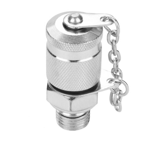
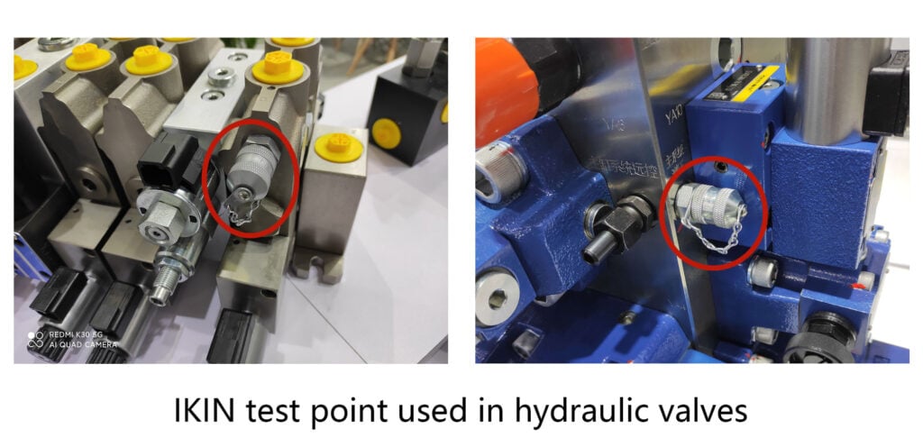
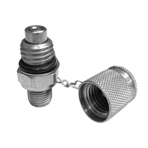
Source - Punto di prova idraulico
Frequently Asked Questions (FAQs)
What are the common test coupling thread options for fluid systems?
When dealing with the thread combinations when using common testing equipment there are several options such as NPT, BSP or metric threads which are and selected thread as well as pressure required will depend on its into the design of the hardware Testing and evaluating the system involves determining leakage rates by examining the range of suitable thread such as the number of threads per inch and the associated diameter of the threads. If there is any possibility of leaks due to the materials used in line, also be experienced air or gas pressure.
How do I determine the correct thread pitch and size for a test coupling?
Selecting the correct thread pitch and size can be closer to a scientific method that demands the use of gauges and calipers on male and female test pieces to determine how many inches an NPT or equivalent number of these size plugs fits. Any given ably verified thread flats or nut lock prevents any possible adhesion during a pitch or cross-section test. Consideration of the internal as well as external finishes and the wrist’s circle diameter of the male race and the distance from its center line to the center line of the bolt ring thread, shall also affect the assessment of the root’s extent.
Can I use adapters to match different coupling thread options during testing?
Absolutely, connectors are frequently employed for matching threads of various coupling options, for instance making BSP become NPT or passing from metric to inches which provides much room for adjustment while connecting incompatible devices. It is necessary to find out from the vendor or manufacturer how the adapter was tested, and whether it was qualified for the intended pressure and material use. Inappropriate adapters shall introduce potential leak paths or points from the mismatched parts so the test becomes useless. Inspect the threads and seals of the adapters before using them and conduct a soft-pressure test before conducting the full test.
What sealing methods work best with various test coupling thread options?
The sealing methods used in fasteners also include the type of fastener system; for example, NPT threads often need PTFE tape or pipe dope, where BSPT threads need O-rings or a bond type of seals, provided the type form and the thread form fail to offer sealing. Bringing together the perfect seal and its orientation in the application involves some factors including thread type, the pressure classification, the operating temperature, and how well it fits with the media. Too much of the sealant is contraindicated because the excess is likely to get into the sample.