How to operate hydraulic test fittings safely?

How to operate hydraulic test fittings safely?

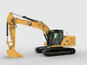
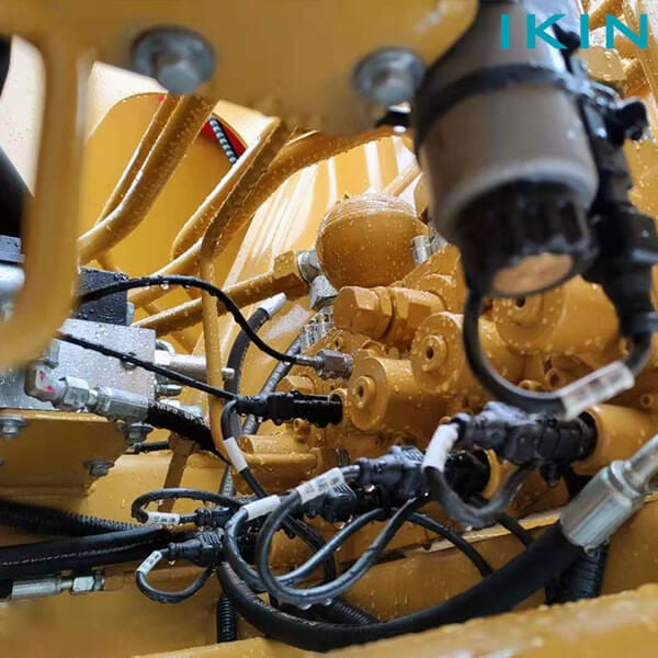
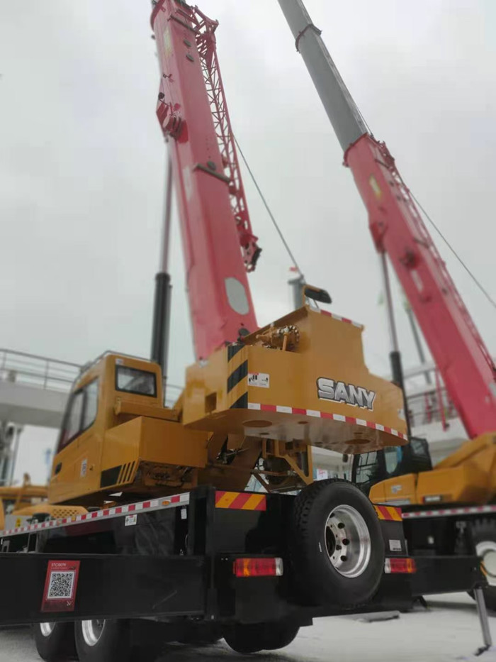
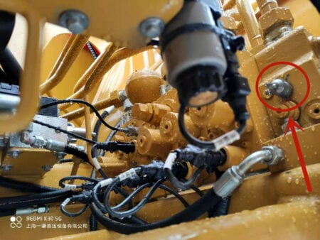
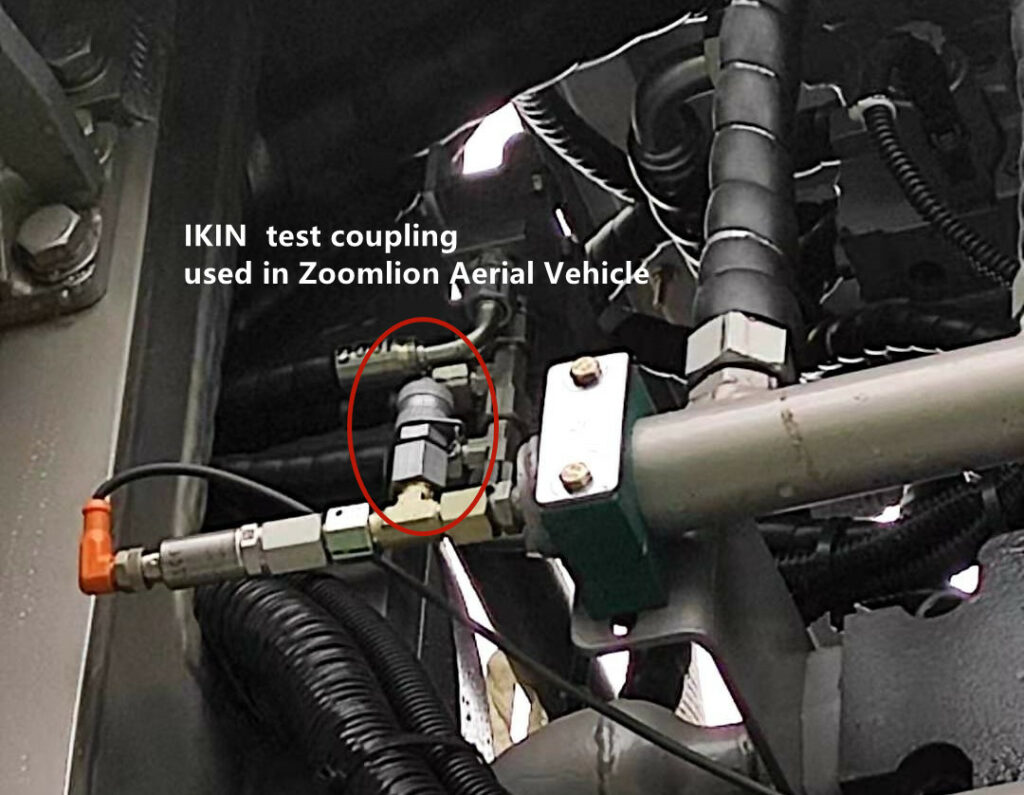
      Hydraulic test fittings are essential components in hydraulic systems, widely utilized in fields such as construction machinery, industrial equipment, aerospace, automotive manufacturing, and oil and gas. 

      Their primary role is to measure and monitor system pressure, ensuring stable operation and safety. However, improper use or poor maintenance can lead to system failures and potentially severe safety incidents.

      Therefore, mastering the safe operation guidelines for pressure measuring joints is crucial. This paper delves into the correct operation and maintenance practices for pressure measurement joints to ensure their safety and reliability in practical applications.

유압 테스트 포트 피팅

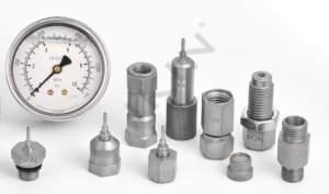
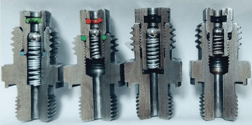
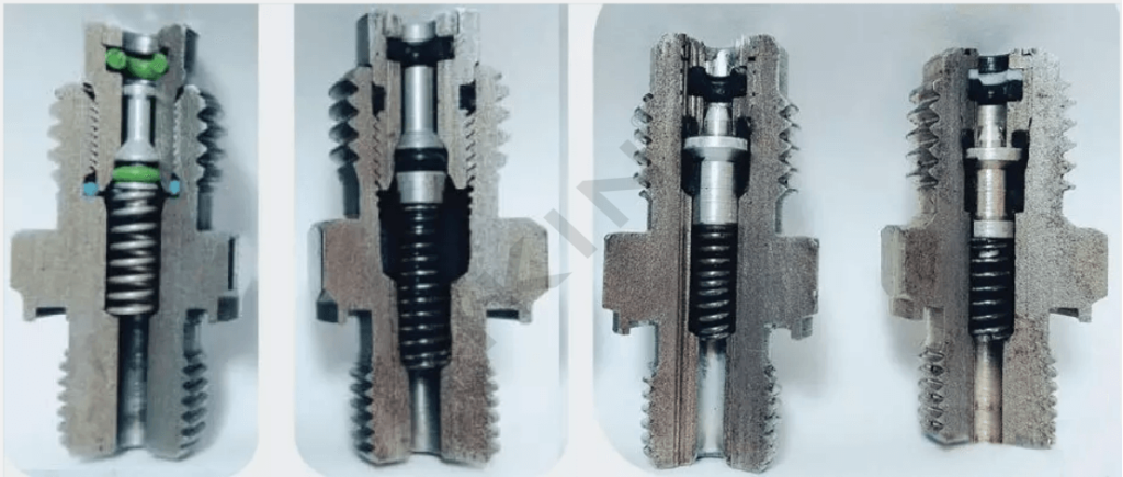
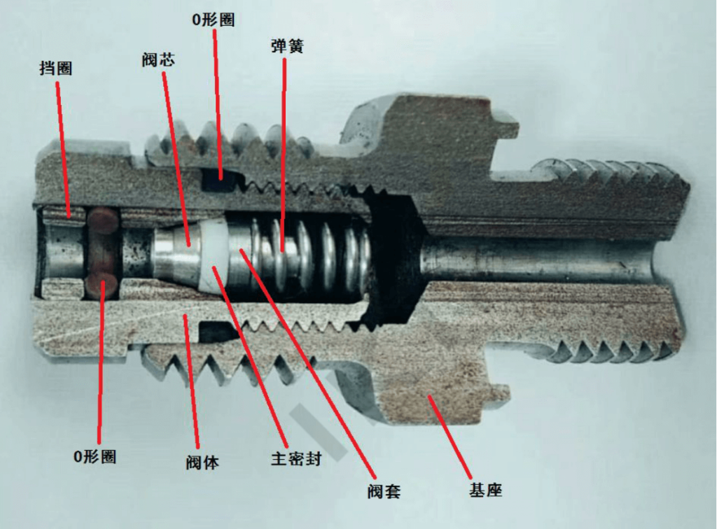
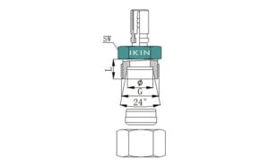
1. Basic structure and operation principle of pressure-measuring connectors

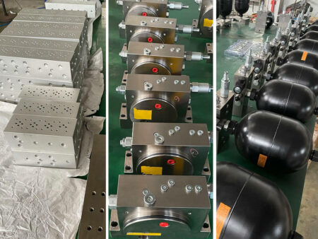
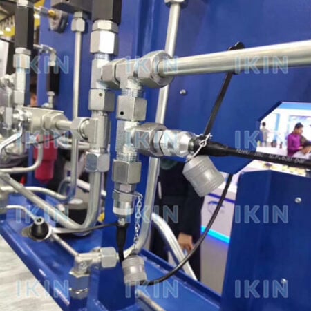
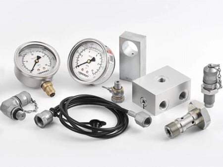
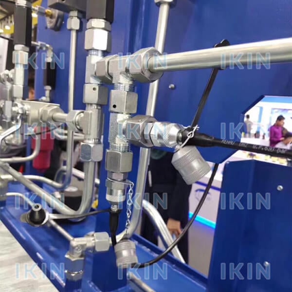
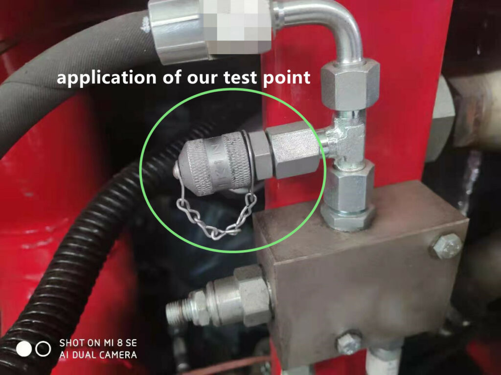
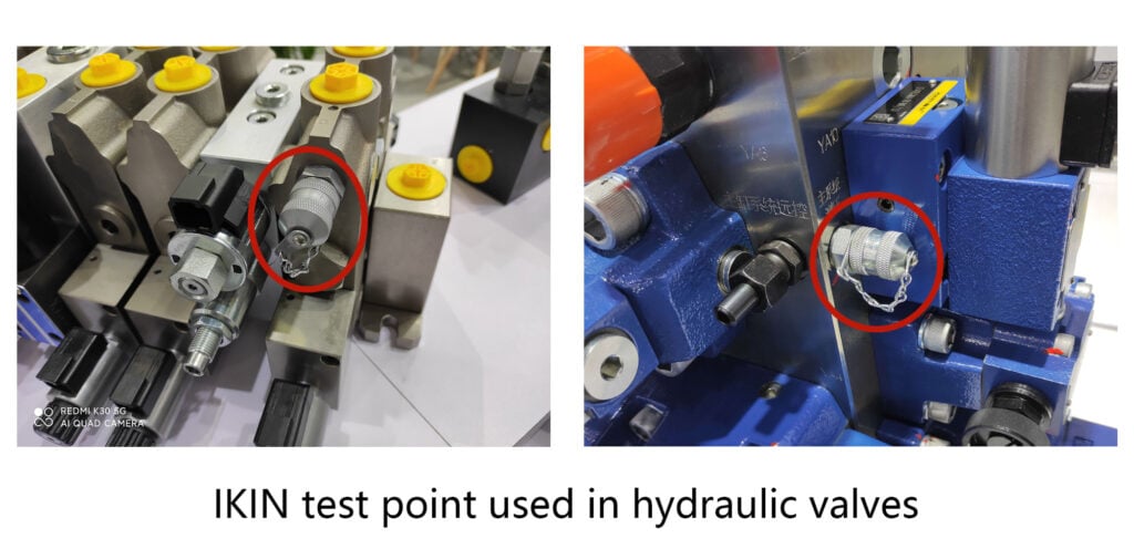
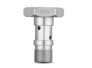
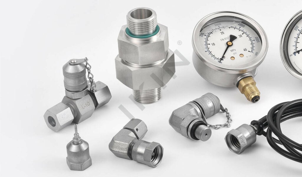
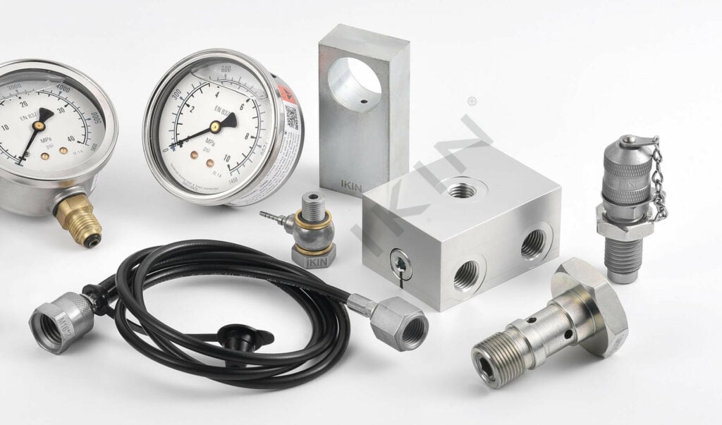
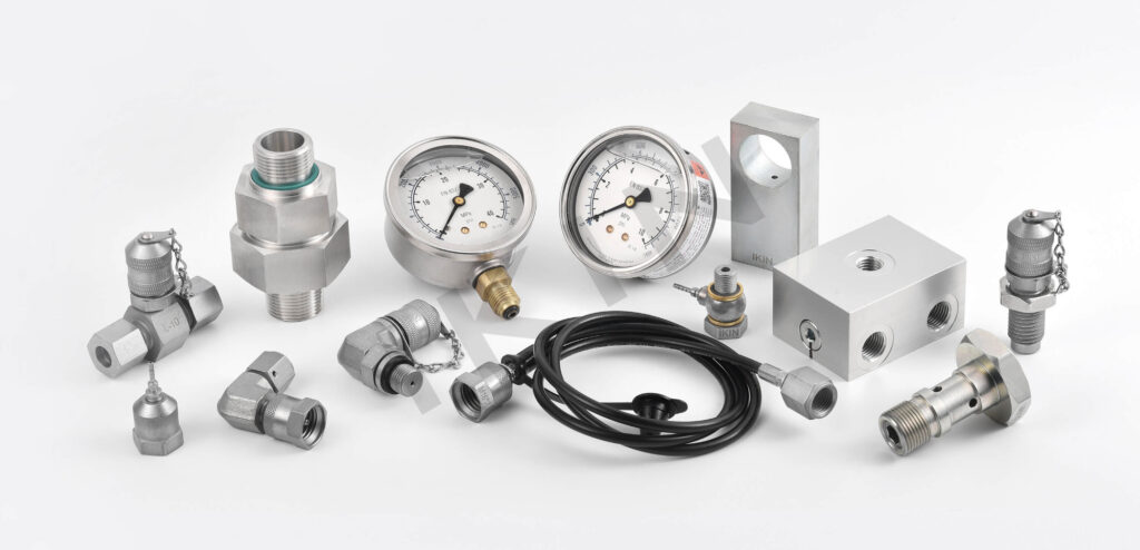
      A pressure measuring fitting typically comprises a body, seals, and connecting components. Its function is to detect pressure fluctuations within a hydraulic system, delivering real-time data that allows operators to monitor and adjust the system’s performance accordingly. Hydraulic test fittings are engineered for optimal tightness and stability in high-pressure environments, effectively preventing fluid leaks and potential system failures.

2. Basic principles of safe operation

2.1 Knowledge of equipment

      Before operating a pressure measuring fitting, it’s essential to thoroughly understand its structure, working principles, and operating instructions. Familiarize yourself with the equipment’s performance parameters, including maximum working pressure, temperature range, and suitable media. This knowledge ensures that the equipment operates within its design limits, preventing any operational issues.

2.2 Wear appropriate protective equipment

      Always utilize suitable protective equipment, such as gloves, goggles, and protective clothing, when operating pressure-measuring fittings. This gear is crucial for preventing injuries from high-pressure fluid leaks and ensures operator safety.

2.3 Checking the status of equipment

      Before operation, thoroughly inspect the condition of the pressure measuring fitting to ensure there are no signs of damage or wear. Pay special attention to the seals, which must be intact to prevent leaks. Additionally, check the connecting parts for tightness to ensure a secure and reliable connection.

manufacturer of hose assembly and fittings/IKIN

3. Safe practices for installation and dismantling

3.1 Installation of hydraulic test fittings

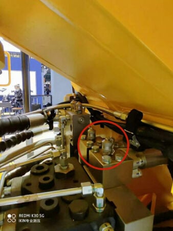
-Selecting an Appropriate Location: Choose a suitable spot within the hydraulic system for installation to ensure the measurement point accurately reflects the system’s operating pressure.

– Cleaning Connecting Parts: Prior to installation, thoroughly clean both the pressure measuring fitting and the system’s connecting parts to remove any impurities or contaminants that might compromise the seal.

– Using the Right Tools: Employ the correct tools for installation and avoid applying excessive force to prevent damage to the fittings or connecting components. Adhere to the equipment manufacturer’s installation instructions to ensure proper setup.

3.2 Disassembly of hydraulic test fittings

– Pressure Relief: Before removing the pressure measurement fitting, ensure that the system is fully depressurized to eliminate any residual pressure and prevent injuries from fluid discharge.

– Equipment Protection: During disassembly, carefully protect the pressure measurement fittings and connecting parts from impacts and damage. After removal, store the connectors properly to prevent contamination and damage.

4. Safety precautions in operation

      Monitoring System Pressure: During operation, continuously monitor the system pressure in real-time to ensure it remains within a safe range. Avoid overpressure conditions to prevent damage to the pressure measuring fitting and the hydraulic system.

      Avoiding Sudden Pressure Changes: Prevent sudden pressure changes during operation to avoid shocks to the pressure measuring fitting and the hydraulic system. Adjust the system pressure gradually to ensure a smooth transition.

      Compliance with Operating Procedures: Adhere strictly to the operating procedures and avoid unauthorized actions. If any abnormal conditions arise during operation, stop immediately, identify the cause, and address it to ensure system safety.

hydraulic hose fittings manufacturers in China

5. Safe practices for maintenance and upkeep

5.1 Regular inspection and maintenance

– Inspection of seals: Regularly inspect the seals of the pressure measuring joints, and replace them in time if they are found to be aged or damaged. Select high-performance sealing materials to improve the sealing effect and service life.

– Cleaning the equipment: Clean the pressure measurement fitting regularly to prevent dust, impurities and corrosive substances from entering the inside of the fitting. Use appropriate cleaning agents and tools to ensure that both the inside and outside of the fitting are kept clean.

5.2 Lubrication and fastening

– Lubrication: For pressure-measuring fittings that require frequent operation, lubricate regularly to reduce wear and operating resistance. Select a suitable lubricant and avoid lubricants that are harmful to the sealing material.

– TIGHTENING: Periodically check the tightness of the joints to ensure that they are securely connected. For loose joints, tighten them with appropriate tools to prevent leakage and system instability.

5.3 RAM

– Maintenance records: Detailed records of each maintenance and servicing, including inspection items, problems found and treatment measures. Through the maintenance records, the history of equipment use can be traced, potential problems can be found and dealt with in a timely manner.

– File management: Establish a file management system for the pressure measuring joints, keep the technical data, operation instructions and maintenance records of the equipment, etc., so as to facilitate the daily management and maintenance.

6. Emergency response measures

Regular Inspection and Maintenance:

  • Seal Inspection: Regularly examine the seals of pressure measuring joints and promptly replace any that are aged or damaged. Use high-performance sealing materials to enhance sealing effectiveness and extend service life.
  • Equipment Cleaning: Routinely clean the pressure measuring fitting to prevent dust, impurities, and corrosive substances from entering. Use appropriate cleaning agents and tools to ensure both the interior and exterior of the fitting remain clean.

Lubrication and Fastening:

  • Lubrication: For pressure measuring fittings that require frequent operation, lubricate regularly to minimize wear and operational resistance. Choose a suitable lubricant and avoid those that could harm the sealing material.
  • Tightening: Periodically check the tightness of the joints to ensure secure connections. Use appropriate tools to tighten any loose joints, preventing leaks and system instability.

Record and Maintenance (RAM):

  • Maintenance Records: Keep detailed records of each maintenance session, including inspection items, identified issues, and corrective actions taken. These records help trace the equipment’s usage history and identify potential problems early.
  • File Management: Establish a file management system for pressure measuring joints, maintaining technical data, operation instructions, and maintenance records. This system facilitates daily management and maintenance activities.

7. Case studies

Case 1: Safe Operation of hydraulic test fittings in a Chemical Plant

      In a chemical plant, numerous hydraulic test fittings were utilized within the hydraulic system. An incident occurred when an operator failed to perform the necessary pressure relief operation, resulting in a high-pressure liquid spray during disassembly and causing injury.

      Following an investigation, the chemical plant developed detailed operating procedures and provided comprehensive training to the operators. These measures significantly improved the operational safety of the pressure measuring joints and prevented similar incidents from occurring.

Case 2: Maintenance of pressure-measuring fittings at a manufacturing company

      A manufacturing company employed high-pressure hydraulic test fittings in its hydraulic press equipment. Due to neglect in timely maintenance and repair, the seals of the pressure-measuring fittings deteriorated and became damaged, leading to system leaks.

      To address the issue, the company took the following actions: replaced all deteriorated seals with high-performance sealing materials; regularly inspected and cleaned the pressure-measuring fittings to ensure optimal condition; and trained operators to enhance their maintenance and operation skills. These measures effectively resolved the leakage problem and improved both the operational efficiency and safety of the equipment.

      Hydraulic test fittings are crucial components in hydraulic systems, and their safe operation and maintenance are directly linked to the stability and safety of the system. By understanding the equipment’s structure, wearing appropriate protective gear, checking the equipment’s condition, installing and removing it correctly, monitoring system pressure, avoiding sudden pressure changes, adhering to operating procedures, conducting regular inspections and maintenance, maintaining thorough records and files, and implementing emergency response measures, you can ensure the safety and reliability of pressure-testing fittings in practical applications.

      Real-world case studies demonstrate that following scientific operation and maintenance protocols not only enhances the service life and performance of pressure measuring joints but also effectively prevents safety incidents. Therefore, attention to the safe operation specifications of pressure measuring joints is essential for ensuring the stable operation of hydraulic systems and the safety of operators.

Common problems and solutions during pressure testing

압력 체크 커플링 제조업체

Common problems and solutions during pressure testing

     Pressure testing is essential for ensuring the proper operation and safety of hydraulic systems and equipment. It helps detect weaknesses, verify design pressures, and identify potential leaks within the system.

      However, various issues may arise during pressure testing. If these problems are not addressed promptly and effectively, they can affect test results and even jeopardize system safety.

      This article provides an in-depth analysis of common problems encountered during pressure testing and offers practical solutions. We will also discuss these issues through real-world examples. By offering detailed analysis and discussion, this article aims to provide practical guidance to ensure the stability and safety of hydraulic systems.

**1. Common problems during pressure testing**

**1.1 Leakage**

      Leaks are among the most common issues encountered during pressure testing. They can occur at system connections, seals, or along piping. The causes of leaks are varied and may include deteriorated seals, improper installation, or defective materials.

**Solutions:**

      Inspection and Replacement of Seals: Regularly inspect the condition of seals. Any seals that are deteriorated or damaged should be promptly replaced to prevent potential leakage.

      Correct Installation: Ensure that all connections and piping are installed correctly, using appropriate methods and tools. Proper tightening and sealing of each component are essential to prevent leaks.

      Material Selection: Choose materials that are corrosion-resistant and capable of withstanding high pressures. Selecting the right materials for the system’s working environment enhances the overall reliability of the system.

      By implementing these solutions, the likelihood of leaks can be significantly reduced, ensuring the integrity and safety of the hydraulic system during pressure testing.


유압 테스트 포인트 커넥터

**1.2 Pressure fluctuations**

      Pressure fluctuation refers to unstable pressure during testing, which can be caused by poor system design, unstable pressure sources, or equipment failure.

**Solutions:**

      Optimized System Design: Ensure that the system is well-designed to prevent sudden changes in pressure. A robust design minimizes the likelihood of pressure fluctuations and significantly reduces associated problems.

      Stable Pressure Source: Utilize a reliable pressure source that can provide continuous and stable pressure, ensuring the system operates normally and efficiently.

      Equipment Maintenance: Conduct regular inspections and maintenance of pressure source equipment. Timely identification and resolution of potential issues are crucial to maintaining optimal working conditions and preventing pressure instability.

      Implementing these solutions will help stabilize pressure during testing, ensuring the system’s reliability and accuracy.

**1.3 Inaccurate meter readings**

      During pressure testing, inaccurate meter readings can compromise the accuracy of the test results. This issue may arise due to improper calibration of the gauge, incorrect mounting position, or gauge malfunction.

**Solutions:**

      Periodic Calibration of Meters: Calibrate the meters at regular intervals to maintain accurate readings and ensure the reliability of the test data.

      Select an Appropriate Mounting Location: Install the meter in a suitable location that minimizes vibration and interference, which can affect the accuracy of the readings.

      Replacement of Malfunctioning Meters: Promptly replace any malfunctioning meters to maintain the accuracy and integrity of the test results.

      By addressing these factors, the accuracy of meter readings can be ensured, thereby enhancing the reliability of the pressure test outcomes.

HYDRAULIC 테스트 포인트 제조업체

**1.4 Temperature effects**

      Temperature variations can significantly impact pressure test results, particularly in extreme high or low-temperature environments. These fluctuations can cause materials to expand or contract, affecting the system’s sealing and pressure stability.

**Solutions:**

      Selection of Temperature-Resistant Materials: Choose materials that are resistant to temperature changes based on the system’s working environment. This ensures that the system maintains stable performance under extreme temperature conditions.

      Implement Temperature Compensation Mechanism: Introduce a temperature compensation mechanism during testing to minimize the impact of temperature fluctuations on the results. This helps ensure the accuracy and reliability of the pressure tests.

      By addressing temperature-related issues, the stability and accuracy of pressure test results can be significantly improved.

**1.5 Connectivity issues**

      Connection problems are a common challenge during pressure testing, often caused by mismatched fitting types, improper installation, or loose connections.

**Solutions:**

      Selecting the Appropriate Fitting Type: Choose fittings that are compatible with the system design and suitable for the working environment to ensure proper matching with the rest of the system.

Correct Installation of Fittings: Follow standard methods and procedures for installing fittings to ensure a secure and reliable connection.

      Regular Inspection and Tightening: Conduct periodic inspections of connection points and promptly tighten any loose parts to maintain a solid and dependable connection.

      By addressing these connection issues, the reliability and effectiveness of pressure testing can be significantly enhanced.

**2. Solutions for pressure testing**

**2.1 Development of a Detailed Test Plan**

      Before conducting a pressure test, it is crucial to develop a comprehensive test plan that outlines the purpose, scope, methodology, steps, and expected outcomes. A detailed test plan helps clarify the objectives and ensures that the testing process is systematic and organized.

**2.2 Use of High-Quality Test Equipment**

      Using high-quality test equipment is essential for obtaining accurate and reliable results. Select certified and calibrated equipment, and ensure that it is in optimal working condition before use.

**2.3 Training and Education**

      Provide thorough training and education for operators to equip them with the necessary knowledge and skills for pressure testing. Training should cover the use of test equipment, execution of test procedures, and identification and resolution of common issues.

**2.4 Recording and Analysis**

      During the pressure test, meticulously record all data and results, including pressure, temperature, time, and environmental conditions. Analyzing this data helps identify potential problems and implement timely corrective measures.

**2.5 Development of Contingency Plans**

      Develop a comprehensive contingency plan to address any emergencies that may arise during the testing process. The plan should include procedures for handling leaks, equipment failures, and safety measures to ensure the testing process remains safe and efficient.

      By implementing these strategies, the reliability and accuracy of pressure testing can be significantly enhanced, ensuring the safe and effective operation of hydraulic systems.

**3. Case Studies**

**Case 1: Pressure Testing in a Chemical Plant**

      During the pressure testing of a new piping system at a chemical plant, multiple leaks were detected. Upon investigation, it was determined that the primary causes of the leaks were aging seals and improper installation. To address these issues, the chemical plant implemented the following measures:

      – Replaced all deteriorated seals with corrosion-resistant, high-performance sealing materials to enhance durability and reliability.

      – Conducted a thorough inspection and tightening of all connections to ensure that the installation complied with relevant codes and standards.

      – Provided comprehensive training to operators to enhance their installation and operational skills.

      By taking these steps, the chemical plant effectively resolved the leakage issues and ensured the safety and stability of the piping system.

**Case II: Pressure Testing in a Pharmaceutical Company**

      During a pressure test of the hydraulic system at a pharmaceutical company, significant pressure fluctuations were detected. Analysis revealed that these fluctuations were caused by an unstable pressure source and poor system design. To address these issues, the pharmaceutical company implemented the following measures:

      – Replaced the existing pressure source with more stable equipment to ensure a continuous and stable pressure supply.

      –  Redesigned the hydraulic system, optimizing the piping layout and connections to enhance overall system stability.

      – Introduced an automated control system to monitor and regulate pressure in real-time, ensuring consistent system pressure.

      By implementing these measures, the pharmaceutical company successfully resolved the issue of pressure fluctuations, significantly improving the operational efficiency and stability of the hydraulic system.

**Case IV: Pressure Testing at an Aerospace Company**

      During pressure testing of an aircraft hydraulic system at an aerospace company, significant effects of temperature variations on the test results were observed. Analysis determined that these temperature changes caused material expansion and contraction, which impacted the system’s sealing and pressure stability. To address this issue, the aerospace company implemented the following measures:

      – Selected temperature-resistant materials suitable for both high and low-temperature environments to ensure stable performance despite temperature fluctuations.

      – Introduced a temperature compensation mechanism during the testing process to adjust system parameters in real-time, ensuring the accuracy of the test results.

      – Controlled the test environment to minimize the impact of temperature variations on the testing process.

      By adopting these measures, the aerospace company successfully mitigated the issues caused by temperature variations, significantly enhancing the accuracy and reliability of the pressure tests.

**Case V: Pressure Testing in a Shipping Company**

      During a pressure test of a ship’s hydraulic system at a shipping company, issues were identified at multiple joints. Inspection revealed that these problems were due to mismatched joint types and improper installation. To resolve these issues, the shipping company implemented the following measures:

      – Selected appropriate fittings that were compatible with the system, ensuring they matched the rest of the hydraulic components.

      – Reinstalled the connectors following correct methods and procedures to guarantee a secure and reliable connection.

      – Conducted thorough inspections and tightened all connections to ensure system stability and safety.

      By taking these steps, the shipping company successfully addressed the connection issues, ensuring the normal operation and reliability of the ship’s hydraulic system.

      Pressure testing is a vital procedure for ensuring the proper functioning and safety of hydraulic systems and equipment. During testing, issues such as leaks, pressure fluctuations, inaccurate gauge readings, temperature effects, and connection problems can arise. These challenges can be effectively managed through the implementation of detailed test plans, the use of high-quality testing equipment, comprehensive operator training, meticulous recording and analysis of test data, and robust contingency plans. These measures ensure the accuracy and reliability of pressure tests.

      Analyzing real-world cases demonstrates that scientific pressure testing methods and strategies not only address issues encountered during testing but also enhance the operational efficiency and safety of hydraulic systems. Therefore, focusing on the identification and resolution of problems during the pressure testing process is crucial for maintaining the stable operation of hydraulic systems.

Hydraulic Pressure Fittings Applied in Various Industries

pressure test fittings

Hydraulic Pressure Fittings Applied in Various Industries

    Pressure measuring fittings are essential hydraulic components. They monitor pressure in hydraulic systems to ensure safety and stability. These fittings are used in many industries, including construction, industrial equipment, aerospace, automotive manufacturing, and oil & gas. Each industry has different performance requirements.

    The performance requirements for pressure measuring fittings differ across industries. Specific examples demonstrate the practical importance of these fittings.

    In this article, we will explore how pressure-measuring fittings are used across various industries. We’ll analyze their key roles and impacts through specific case studies.

유압 밸브에 사용되는 IKIN 테스트 커플링 6

1. In the field of construction machinery

    In the construction machinery industry, pressure measuring fittings are indispensable components. Equipment such as excavators, bulldozers, and loaders must endure harsh environments for extended periods, demanding highly reliable hydraulic systems.

    Pressure measuring fittings play a critical role by continuously monitoring hydraulic system pressure in real time. This real-time monitoring ensures that the equipment operates within the optimal pressure range, thereby enhancing reliability, preventing system failures, and maintaining peak performance and safety.

    Excavators, bulldozers, loaders, and similar equipment often operate in harsh environments for prolonged periods. This demanding usage necessitates exceptional reliability in their hydraulic systems. To achieve this, pressure measuring fittings are employed to monitor the hydraulic system’s pressure in real time. These fittings ensure that the equipment operates within the optimal pressure range, thereby preventing potential system failures and maintaining peak performance and safety standards. 

**Case Study: Excavator Application**

    A leading construction machinery company incorporates high-performance pressure measuring fittings in the hydraulic systems of its excavators. Given that excavators are required to function in high-intensity work environments, the pressure resistance and durability of these fittings are crucial.

    These pressure measuring fittings are crafted from the latest high-strength alloy materials and utilize advanced sealing technology. This design enables them to perform reliably for extended periods under high-pressure and high-temperature conditions, effectively preventing leaks and system failures.

    Through regular maintenance and servicing, the company’s excavators have significantly enhanced their operational efficiency and safety. The robust construction of these fittings ensures that the hydraulic systems remain reliable, thereby optimizing performance and reducing downtime. This meticulous approach to equipment maintenance has contributed to the company’s reputation for producing durable and efficient machinery capable of withstanding the rigors of demanding construction environments.

2. **Industrial Equipment Sector**

    Industrial equipment such as hydraulic presses, die casting machines, and injection molding machines heavily rely on pressure measuring fittings. These fittings ensure the systems operate smoothly under high pressure and high temperature conditions. They provide accurate pressure data, enabling operators to adjust system parameters in a timely manner. This real-time data optimizes equipment performance and ensures an efficient, stable production process.

**Case Study: Hydraulic Press Application in a Manufacturing Company**

    A manufacturing company has implemented new high-pressure gauge fittings in its hydraulic press equipment. Precise pressure control is essential for hydraulic presses during production, making the accuracy and stability of these fittings crucial.

    By utilizing high-performance pressure measuring fittings, the company has notably enhanced the quality of its hydraulic products. This improvement has led to a significant reduction in scrap rates and an increase in production efficiency. The reliable performance of these fittings ensures that the hydraulic presses maintain consistent pressure control, thereby optimizing the overall manufacturing process and ensuring high-quality output.

    3. **Automobile Manufacturing Sector**

    In the automotive manufacturing sector, hydraulic systems play a crucial role in braking, steering, and suspension systems. Pressure measuring fittings are essential for real-time pressure monitoring in these systems, ensuring the vehicle’s safety performance under various operating conditions.

**Case Study: Braking System Application for an Automobile Manufacturer**

   A renowned automobile manufacturer has integrated intelligent pressure measurement fittings into the braking system of its latest models. These advanced fittings combine a pressure sensor with data transmission capabilities, allowing real-time pressure data to be sent to the vehicle’s electronic control system. This continuous data stream enables the system to dynamically adjust brake pressure, significantly enhancing braking performance and vehicle safety.

    The manufacturer has also conducted extensive testing and validation to ensure these pressure-measuring fittings maintain optimal performance across different climatic conditions and driving environments. This rigorous testing ensures that the fittings provide consistent, reliable data, contributing to a safer and more dependable driving experience for consumers. By incorporating these intelligent fittings, the automaker has improved the overall safety and reliability of its vehicles, reinforcing its commitment to quality and innovation in automotive design.

    4. **Oil and Gas Sector**

    In the oil and gas industry, hydraulic systems must function in complex environments with significant pressure fluctuations and exposure to corrosive media. Pressure measuring fittings are critical in these systems for monitoring the pressure of pipelines and equipment, preventing safety incidents such as leaks and explosions.

**Case Study: High-Pressure Pipeline Application in an Oilfield Project**

    An oilfield project implemented high-pressure gauge fittings within its pipeline system. These fittings, constructed from high-strength alloys and featuring multi-layer seals, are engineered to withstand high-pressure and highly corrosive environments over extended periods. Regular inspections and maintenance have enabled the project team to avert numerous potential leakage incidents, ensuring safe production and environmental compliance.

    Additionally, these pressure measuring fittings are equipped with remote monitoring technology, allowing operators to observe real-time pressure changes in the pipeline from a central control room. This capability ensures that any abnormalities are quickly addressed, significantly enhancing production efficiency and safety management in the oilfield. The integration of these advanced fittings not only ensures the structural integrity of the pipeline system but also supports the overall safety and efficiency of the oilfield operations.

Ikin 테스트 포인트 호스 응용 프로그램 1

   5. **Building Construction Sector**

    In the building construction sector, large mechanical equipment such as tower cranes and concrete pump trucks rely on stable hydraulic systems for optimal performance. Pressure measuring fittings are crucial in these hydraulic systems to ensure stability and safety during construction activities5.

**Case Study: Tower Crane Application for a Construction Company**

     A construction company has integrated high-precision pressure measurement fittings into the hydraulic systems of its tower cranes. During construction, tower cranes frequently lift heavy loads, demanding extremely stringent pressure requirements for their hydraulic systems. By employing high-performance pressure measuring fittings, the company has significantly enhanced construction efficiency and safety in large-scale projects.

    These advanced pressure measuring fittings feature the latest self-locking design, ensuring that the fittings remain secure under high pressure and vibration. This innovation greatly improves the reliability and operational safety of construction equipment, enabling the tower cranes to function seamlessly in demanding environments. Consequently, the construction company has achieved higher productivity and reduced risks, reinforcing the importance of utilizing top-tier pressure measuring fittings in critical construction machinery.

6. **Agricultural Machinery Sector**

    In the agricultural machinery sector, equipment such as tractors, harvesters, and planters rely heavily on hydraulic systems. Pressure measuring fittings are essential for monitoring and controlling these hydraulic systems, ensuring the machines’ reliability and efficiency in various farming operations.

**Case Study: Harvester Application for an Agricultural Machinery Company**

    An agricultural machinery company has implemented a new type of pressure measuring connector in the hydraulic system of its latest harvester model. These advanced fittings allow operators to monitor the hydraulic system’s status in real time, enabling timely adjustments and maintenance. As a result, the harvester performs reliably in field operations, reducing mechanical failures and enhancing harvesting efficiency.

    These pressure measuring fittings feature an anti-fouling design that effectively prevents soil and impurities from entering the system. This design keeps the hydraulic system clean and functioning properly, ultimately improving the efficiency and service life of the agricultural machinery.

    By adopting these innovative fittings, the company has ensured that its harvesters deliver optimal performance, contributing to more productive and efficient farming operations.

Ikin 테스트 포인트 호스 애플리케이션 2

7. **Mining Sector**

    The mining industry is highly demanding, and hydraulic systems are crucial for the performance of mining equipment. Pressure measuring fittings are essential for monitoring the hydraulic systems in this sector, ensuring stable operation under high loads, high pressures, and harsh environmental conditions.

**Case Study: Hydraulic Drilling Rig Application for a Mining Company**

    A mining company has integrated high-performance pressure measuring couplings into the hydraulic systems of its drilling rigs. These couplings are made with special wear-resistant materials and a multi-layer sealing structure, allowing them to operate reliably for extended periods under high-pressure and high-vibration conditions.

    Through regular maintenance and real-time monitoring, the company’s hydraulic drilling rigs perform exceptionally well in deep well drilling and ore extraction. This significantly boosts both efficiency and safety. The use of these advanced pressure measuring couplings not only extends the lifespan of the equipment but also reduces downtime caused by equipment failures, thereby improving overall productivity at the mine. By leveraging these robust fittings, the mining company ensures that its drilling operations are more efficient, reliable, and productive.

    The case studies above clearly illustrate the application of pressure measuring fittings across various industrial fields, highlighting their critical role in ensuring the stable operation and safety of hydraulic systems. These fittings help enterprises improve productivity, reduce maintenance costs, and enhance safety.

IKIN 압력 테스트 포인트

    As technology continues to advance, the performance and functionality of pressure measuring fittings are also improving. This progress will lead to their application and promotion in even more fields in the future, making significant contributions to industrial development and technological progress.

    By integrating these advanced fittings, industries can look forward to more efficient, reliable, and safe hydraulic systems, driving further innovation and growth.

Pressure Measuring Fittings in Hydraulic Systems: Types, Applications, and Best Practices

we offer test hose&couplings just as minimess

Pressure Measuring Fittings in Hydraulic Systems: Types, Applications, and Best Practices

        Hydraulic systems are essential in modern industry, playing a crucial role in fields such as construction machinery, industrial equipment, aerospace, and automotive manufacturing.

        At the heart of these systems lies the pressure measuring fitting, which is critical for measuring and monitoring system pressure to ensure stability and safety.

In this comprehensive guide, we will explore the various types of pressure measuring fittings, their application scenarios, selection criteria, installation and maintenance procedures, and real-world case studies demonstrating their importance in hydraulic systems.

pressure test fittings

Pressure measuring fittings come in various designs tailored for specific applications, each with unique features:

1. Quick couplings

 ·Characteristics: Designed for rapid connection and disconnection.

 ·Applications: Used in hydraulic systems requiring frequent assembly and disassembly, enhancing efficiency through simple insertion and removal.

퀵 커플러 제조업체 IKIN

2. Threaded joints

   ·Characteristics: Secured by threaded connections, suitable for high-pressure environments.

   ·Applications: Common in systems needing robust connections that can withstand high pressure and vibration.

3. Push-in fittings

 ·Characteristics: Connect via a simple push-in operation.

 ·Applications: Ideal for low and medium pressure systems, though caution is needed in high-pressure environments.

4. Flanged joints

 ·Characteristics: Provide high-strength connections.

 ·Applications: Used in heavy machinery and high-pressure pipelines due to their strong connections and excellent seismic.

5. Welded joints

·Characteristics: Connected by welding, suitable for high-pressure and high-temperature conditions.

·Applications: Preferred in environments demanding high connection strength, despite more complex installation and maintenance.


When selecting a pressure measurement fitting, a number of factors need to be thoroughly evaluated to ensure optimum performance and long-lasting reliability in a particular application. The main factors to consider include the following:


1. Pressure range

 According to the working pressure of the hydraulic system, select the coupling that can withstand the corresponding pressure. Over-pressurization can lead to damage to the couplings and even safety accidents.

   When choosing, you need to carefully check the maximum working pressure of the hydraulic system and the rated pressure of the pressure measurement joints to ensure that the joints can withstand the working pressure of the system.


2. Temperature range

 Hydraulic systems may operate in high or low temperature environments, requiring the selection of fittings with good temperature resistance.

    Pressure gauge fittings made of different materials have different performance in different temperature ranges, and you need to choose the right fittings according to the operating temperature of the hydraulic system.


3. Media type

 According to the medium used in the hydraulic system (such as oil, water, etc.) to select the appropriate joint material to prevent corrosion and media leakage.

   Different media have different requirements for pressure measurement joint materials, such as oil-based hydraulic media suitable for the use of metal joints, while water-based hydraulic media may require the use of corrosion-resistant materials.


4. Connectivity

 According to the design and installation requirements of the system to choose the appropriate connection, such as quick couplings, threaded fittings or push-in fittings. The selection needs to take into account the connection method and operating habits of the hydraulic system to ensure that the fitting is easy to install and use.

In order to ensure that the gauge fitting will operate consistently and efficiently in the hydraulic system for a long period of time, proper installation methods and a systematic maintenance program are essential. Below are some detailed recommendations:

1. Installation steps

   – Ensure that the hydraulic system is fully pressurized before installation.

   – Select the appropriate installation tool according to the type of fitting.

   – Ensure that fittings are clean and free of foreign matter where they connect to the system.

   – Install the fitting correctly according to the product instructions to ensure a good seal.

   – Pressure test after installation to ensure that the joints are leak-free.


2. Maintenance methods

   – Regularly check the sealing of the joints and replace the seals when leaks are detected.

   – Clean fittings regularly to prevent dust and contaminants from entering the system.

   – Regularly lubricate frequently used joints to ensure smooth operation.

   – When used under high pressure or in harsh environments, periodically check the fittings for wear and replace damaged fittings in a timely manner.

유압 시스템 3에 사용되는 IKIN 테스트 커플링

In the hydraulic system, the pressure measuring fitting is not only widely used, but also plays a vital role. Through the following case studies of several practical applications, we can have a clearer understanding of the key role and significant results of the pressure measurement joints in various industries.

        #Construction machinery

A major construction machinery company has introduced a new type of pressure measurement joint in its excavator hydraulic system. Made with high-precision sensors and durable materials, the connector provides excellent measurement accuracy and durability.

By using this pressure fitting, the company monitors the hydraulic system pressure in real time to ensure that the equipment operates within the optimal pressure range, improving efficiency and safety.

In addition, the corrosion and pressure resistance of the couplings significantly reduces maintenance costs, extends service life, and improves overall productivity.


#Oil and gas

In the oil and gas industry, a large oilfield project has adopted a high-pressure and corrosion-resistant pressure measuring fitting to monitor the pressure of high-pressure pipelines. The application of this pressure fitting effectively prevents safety incidents such as pipeline leaks and explosions, and improves the safety and productivity of the project.

Installed at key pipeline nodes, these couplings transmit real-time pressure data to the monitoring center, helping operators adjust system parameters in a timely manner to prevent potential hazards.

#Industrial equipment

An industrial equipment manufacturing company has installed a variety of pressure measurement fittings in its hydraulic presses to monitor the pressure of the equipment’s hydraulic system.

Through accurate pressure monitoring and data analysis, the company identified and resolved potential problems in the hydraulic system and made timely adjustments, significantly improving the equipment’s operational stability and service life.

The real-time data provided by the pressure measurement couplings supports predictive maintenance, reduces equipment failure rates and downtime, and improves overall productivity.

Ikin 테스트 포인트 호스 애플리케이션 2

Pressure gauge fittings play a vital role in hydraulic systems, and their proper selection, installation and maintenance are the keys to ensuring the safe and stable operation of hydraulic systems. By understanding the different types of pressure measuring fittings and their application scenarios, and mastering the selection and maintenance methods, the operating efficiency and safety of the hydraulic system can be effectively enhanced.

        We hope this article can help you better understand the basics and practical application scenarios of pressure measuring fittings, as well as grasp the key methods of selection and maintenance. We hope this information will be helpful to hydraulic system engineers and technicians in their work to enhance the performance and reliability of hydraulic systems. If you have any questions or need further guidance, please feel free to contact a professional.

시장에서 유압 테스트 커플 링의 차이점은 무엇입니까?

IKIN FLUID 수압 테스트 포인트 커플링

중국 3대 제조업체

수압 테스트 피팅 공급업체

SGS 승인

시장에서 압력 테스트 포인트의 구조는 무엇입니까?

압력 테스트 포인트는 작고 불필요해 보이지만 유압 테스트 시스템은 훨씬 더 편리할 것입니다. 

1. 압력 테스트 포인트의 기능

압력 테스트 포인트는 주로 유체 시스템의 압력을 측정하는 데 사용되며 내부에 자체 밀봉 밸브가 있습니다.

단독으로 사용하면 스프링의 작용으로 시스템 매체의 누출을 막을 수 있습니다.

자체 밀봉 밸브는 골무 또는 압력 센서가있는 측정 호스에 연결 한 후 열 수 있으며 시스템 압력 매개 변수는 시스템 압력 감지, 시스템 디버깅 및 오류 진단에 사용되는 압력 게이지 또는 테스터로 표시 될 수 있습니다. 고압 또는 저압 유체 시스템.

특수 위치에 설정하면 테스트 포인트 어댑터를 유압 시스템 매체 샘플링, 시스템 압력 완화 및 시스템 배기에도 사용할 수 있습니다.

2. 시장에서 압력 테스트 포인트의 분류

압력 테스트 포인트 커넥터는 압력 측정 및 고 / 저 유량 유체 샘플링을 위해 특별히 설계 되었기 때문에 설계는 압력 범위를 충분히 고려했습니다.

그리고 다양한 사용 범위에 따라 다양한 유형과 강점의 테스트 포인트가 설계되었으며 이러한 커넥터는 작업에서 대체 할 수없는 역할을합니다.

다른 내부 구조에 따라 압력 테스트 포인트 구조는 볼 씰, 피스톤 씰 및 콘 씰로 나눌 수 있습니다.

2.1 볼 씰 구조

볼 씰 압력 테스트 커플 링은 주로 스틸 볼과 스프링으로 구성됩니다.

추력은 스프링 사전 압축에 의해 생성되므로 강철 볼이 밸브 본체 결합 표면에 대해 눌러져 밀봉됩니다.

볼 씰 구조의 특징 : 간단한 구조, 기계적 씰, 노화하기 쉽지 않고 안정성이 좋습니다.

또 다른 특징 : 밸브 바디 접촉면의 가공 정확도가 높아야하고, 스틸 볼과 밸브 바디가 라인 접촉 상태이며, 씰링 효과는 평균입니다.

수압 시험 포인트 볼 씰 구조

볼 씰이있는 압력 테스트 포인트의 내부 구조

2.2 피스톤 씰 구조

피스톤 씰 압력 테스트 포인트 어댑터는 주로 피스톤, O- 링 및 스프링으로 구성됩니다. 씰링 링은 피스톤 홈에 있습니다.

스프링 사전 압축 추력을 통해 씰링 콘 (방사형 씰) 또는 평평한 표면 (축 씰)에 부착하십시오.

볼 씰 압력 테스트 커플 링의 내부 구조

2.3 콘 실링 구조

콘 씰 압력 테스트 커플 링은 콘 밸브 코어, 콘 씰 및 스프링으로 구성됩니다.

원추형 씰과 원추형 밸브 코어는 스프링의 사전 압축 추력 아래에서 밸브 본체의 원추형 결합 표면에 단단히 부착됩니다.

Cone-sealed 압력 테스트 포인트의 내부 구조

콘 밀폐 압력 시험의 내부 구조

콘 씰 특징 : 원추형 밸브 코어와 원추형 씰이 함께 작동하고 씰링이 표면 접촉이며 씰링 효과가 더 좋고 가스와 액체가 보편적입니다.

스프링은 밸브 본체에 통합되어 있으며 풀기가 쉽지 않습니다. 그러나 밸브 몸체와 스풀의 처리 정확도는 상대적으로 높습니다.

업계에서 일반적으로 사용되는 장비로서 유체 압력 테스트 포인트는 광범위한 실제 범위와 편리한 연결 및 샘플링으로 유명합니다. 특히 고압 및 유속에서 유체를 사용하는 경우 많은 장점과 편리함이 있습니다.

그렇다면 장점은 무엇입니까?

장점 1 : 작업은 고압에서 수동으로 완료 할 수 있습니다.

유체가 고압 상태 일 때 작동이 부주의하면 고압이 쉽게 액체가 누출되어 돌이킬 수없는 공정 사고를 일으키고 생명을 위협 할 수 있습니다.

그러나 압력 테스트 호스 커넥터는이를 충분히 고려하여 고압 상태에서 양손으로 간단히 커넥터를 분리하고 닫을 수 있습니다.

장점 2 : 작은 구조

샘플링 및 압력 테스트 위치는 고정되지 않는 경우가 많기 때문에 특정 조건 및 요구 사항에 따라 작업을 수행해야합니다.

따라서 콤팩트 한 형태는 운반 및 엔지니어링에 큰 편의를 제공합니다.

그런 다음 미터와 쉽게 연결할 수있는 기능이 있습니다.

고유 한 목적으로 인해 악기와의 연결을 완전히 고려하여 조작이 쉽고 연결이 견고합니다.

3. 요약

테스트 포인트 어댑터는 유압 시스템의 매우 작은 구성 요소이지만 유압 시스템의 디버깅, 테스트 및 진단에 중요한 역할을 합니다.

압력계 또는 센서를 통해 분해 및 조립없이 다양한 압력 테스트를 완료 할 수 있으며 누출이 없습니다.

유압 시스템에서 압력 테스트 지점 피팅을 합리적으로 설정하면 디버깅, 테스트 및 진단에 많은 편의를 제공합니다.

좋은 적용 효과를 보장하기 위해서는 고품질의 안정적인 제품을 선택하는 것이 매우 중요합니다.

압력 테스트 포인트의 현재 평가가 매우 좋고 제품 디자인이 우수합니다.

큰 유량 출력을 보장하는 동시에 엄격한 품질 심사 기준을 보장하여 제품의 사용 가치를 높일 수 있습니다.

현재 상황에서 볼 때 압력 테스트 커플 링은 주로 다양한 유체 시스템에 유연하게 적용됩니다.

그러나 다른 유체 시스템의 내부 배선과 커넥터의 크기가 다르므로 해당 압력 테스트 지점을 구매하기 전에 미리 흐름 제어를 수행해야합니다.

사이즈가 맞지 않으면 귀찮은 일이기도합니다.

유압 테스트 포트 피팅

이킨 플루이드

—— 중국 최고의 3 제조업체, 수압 테스트 포인트 전문

당신이 찾을 수있는 혜택 이킨에서

공장 가격과 낮은 moq

신뢰할 수있는 품질, Eaton, Hawee 등의 공급 업체

100% 누출 검사 완료 전

3년 보증

대량 배송의 경우 영업일 기준 10일

minimess, stauff 등과 같은 다른 피팅과 일치

콘 씰 디자인 구조, 안정적이고 긴 수명

무료 샘플 받기

2일 안에

*우리는 귀하의 기밀을 존중하며 모든 정보를 보호합니다.

Ikin Fluid는 2020 Bauma China에 참석했습니다.

2020 바우마 차이나

2020 년 바우 마 차이나 상하이를 돌아보세요

11 월 27 일, 4 일간의 Bauma China Shanghai 2020이 성공적으로 종료되었습니다.

코로나 19의 영향에도 불구하고 4 일 연속 비가 내림에도 불구하고 건설 기계 산업의 열정은 여전히 멈출 수 없습니다.

2020 바우마 차이나

주요 건설 기계 회사들은 그들의 능력과 행사의 창의성을 보여 주었고 관객을 압도했습니다.

출품자들은 밝은 점이 많아 더욱 유쾌하게 놀라움을 보여주었습니다.

Sany의 "Online Bauma Show"가 새로운 IP 235 억 주문에 서명되었습니다!

신제품의 데뷔는“트리니티 스틸 군단”의 강점을 보여 주었다.

  • 포괄적 인 규정과 가장 긴 붐을 갖춘 C10 시리즈 새로운 펌프 트럭
  • 새로운 100 톤 대형 굴삭기 SY1250H

  • 25 톤에서 800 톤 크레인까지 Sany의 최신 장비 46 개 모델

  • 운전실이없는 무인로드 롤러

  • 세계 최초의 플러그인 하이브리드 포장기

  • 세계 최초의 대량 생산 전기 굴삭기 및 기타 수십 가지 최첨단 제품이 모두 전면 공격을 받아 관객을 놀라게합니다!

산니 크레인

아래 사진은 Bauma Exihibition에서 Sany 크레인 유압 시스템에 사용 된 IKIN의 테스트 커플 링을 보여줍니다.

다음은 Sany 부스에서의 라이브 촬영입니다. 우리의 IKIN입니다 유압 테스트 커플 링 익숙한 Sany 크레인에서.

W이자형 IKIN 체액 심각하다 설계 및 제조 유압 테스트 포인트에스.

IKIN 테스트 커플링 포인트

"중국의 지혜"로 가득 찬 XCMG "제철 군단"융합

XCMG 그룹은 글로벌 디지털 예비 부품 서비스 정보 시스템 (X-GSS라고하는 XCMG-Global Service System)을 출시했습니다.

디지털, 지능형, 무인 변환 및 업그레이드를 홍보하십시오.

다시 말하지만 IKIN FLUID 압력 체크 테스트 포인트는 XCMG의 부스.

파커 피팅 교체 공급업체

Zoomlion은 첫날 90 억 RMB 이상의 계약을 체결했으며이 신제품은 세계에서 가장 많은 것을 목격했습니다.

  • Zoomlion의 세계에서 가장 높은 자체 추진 직선 암 고소 작업 플랫폼 ZT68J
  • Zoomlion은 많은 "블랙 기술"제품을 전시했습니다.
  • Zoomlion의 새로운 하이테크 제품은 모두 강력한 R & D 및 혁신 능력을 보여줍니다.

다음 그림은 Zoomlion 부스에서 찍은 IKIN 압력 테스트 포인트의 적용을 보여줍니다.

IKIN 압력 테스트 포인트

또한 아래는 다른 많은 고객 부스 전시회에서 사용되는 압력 테스트 커플 링입니다.

HYDRAULIC 테스트 포인트 제조업체
IKIN 수압 테스트 포인트

전염병의 영향을 받아 2018 년보다 쇼에 참여하는 고객 수가 감소했지만 여전히 많은 고객이 파티를 찾는다.

IKIN이 정성스럽게 준비한 과학과 기술의 감각을 담은 전문 전시회는 많은 고객의 관심을 끌었습니다.

IKIN 부스

압력 테스트 포인트용 시험기
IKIN 테스트 포인트 어댑터
Bauma China IKIN 부스
IKIN 부스 고객
유압 테스트 포트 피팅
유압 테스트 포인트 커넥터
프레스 체크 테스트 포인트
hydraulic test hose&couplings

유압 호스 피팅의 유형과 고장 분석은 무엇입니까?

중국의 Banjo 피팅 제조업체와 유압 호스 피팅

중국 3대 제조업체

유압 테스트 포인트 호스 공급 업체

SGS 승인

유압 호스 어셈블리 및 피팅의 유형은 무엇입니까?

중국 건설 기계의 급속한 발전으로 유압 호스 어셈블리의 신뢰성은 업계에서 가장 우려되는 문제 중 하나가되었습니다.

유압 호스 어셈블리는 유압 전송 시스템의 기본 요소입니다. 호스 어셈블리의 품질은 유압 시스템과 메인 엔진의 성능에 직접적인 영향을 미칩니다. 호스 어셈블리 고장의 일부는 조인트 코어의 구조에서 비롯됩니다.

호스 커넥터 코어는 주로 SAE 표준, ISO 표준 및 KES 표준을 기반으로하는 연결 구조입니다. 다른 부분은 압착 부 (꼬리 구조)의 구조로, 호스의 외부 재킷과 내부 및 외부 고무층과 일치하여 호스 어셈블리의 성능을 충족시키기 위해 신뢰할 수있는 압착 변형을 형성합니다.

이음 심 압착 부의 구조가 호스의 종류에 따라 설계가 부적절 할 경우 제품 품질 문제가 크게 발생합니다.

따라서 다른 작업 환경에서 호스에 대해 선택된 (설계된) 조인트 코어의 유형도 다르며 합리적인 설계로 고장 발생을 피하거나 줄일 수 있습니다.

1. 호스 피팅의 종류와 특징

전체 호스 조립 산업 전반에 걸쳐 호스 조인트와 호스 사이에는 주로 두 가지 유형의 안정적인 연결이 있습니다. 즉, 완전 보류 호스 조인트와 분리형 호스 조인트입니다.

전체 압착 조인트는 압착기의 8 부분 압착 모듈이 조인트 코어, 호스 및 아우터 재킷을 조립 한 후 호스 조인트를 어느 정도 균일하게 압착하여 호스 조인트와 호스가 전체가되도록하는 공정입니다. .

탈착식 호스 커넥터는 외부 콘과 커넥터 코어가있는 커넥터 코어를 통해 호스를 압축하여 호스가 커넥터 슬리브의 내부 콘에 가까워져 더 큰 결합력을 가진 연결을 형성합니다.

1.1 호스 압착 형태 및 특성

호스 보류 유형은 주로 호스 유형 (또는 내부 및 외부 고무의 크기)과 호스 어셈블리의 압력 환경에 따라 다릅니다.

주로 비 필링 고무 압착, 필링 외부 고무 압착, 내부 및 외부 고무 필링 압착의 세 가지 범주로 나뉩니다.

각 유형의 특성은 다음과 같습니다.

(1) Non-peeling 및 crimping : 호스의 내부 및 외부 고무를 벗길 필요가 없으며 호스 설치 후 압착으로 제품을 완성 할 수 있습니다. 처리 기술은 간단합니다.

이러한 유형의 크림 핑은 GB / T3683, EN853 및 SAE 표준과 같이 상대적으로 얇은 외부 고무 층이있는 강철 와이어 브레이드 호스에 자주 사용됩니다.

(2) 스트리핑 및 압착 : 호스의 외부 고무층을 일정 길이 (외부 고무층이 두꺼움)로 벗겨야하는데, 이는 강선 보강층이이 홈과 더 잘 접촉하도록하는 데 사용됩니다. 자켓.

외력에 의해 재킷이 수축 및 변형되면 강철 와이어가 단단히 고정되어 고압 충격을받을 때 조인트가 빠지는 것을 방지합니다.

이러한 유형의 압착은 주로 GB / T10544, EN856 및 SAE 표준과 같은 강선 권선 호스에 적용됩니다.

(3) 내부 및 외부 고무 스트리핑 및 크림 핑 : 내부 및 외부 고무 층을 일정 길이 (내부 및 외부 고무의 두께)로 벗겨야하며 강선 층과 내부 고무 층이 물결 모양으로 압출됩니다. 일반적으로 GB / T10544, EN856-R13, R15 등에 적합합니다. 사양 (32 개 이상 32 개 포함) 초고압 강선 나선형 호스.

1.2. 원천 징수 형 호스 커넥터

원천 징수 형 호스 조인트는 주로 조인트 코어, 외부 재킷 (너트는 옵션 부품) 및 기타 부품으로 구성됩니다.

1) 공동 핵심 재료, 유형 및 특성

일반적으로 조인트 코어에 사용되는 재료는 20, 35 및 45 강철입니다. 직선 조인트 코어의 경우 변형에 강한 저항력을 가진 35 및 45 강철이 자주 사용됩니다. 벤딩 조인트 코어의 제조 가능성을 고려할 때 일반적으로 20 또는 35 강이 사용됩니다.

열간 굽힘 기술이 대중화됨에 따라 35 강과 45 강을 팔꿈치 조인트 코어에도 사용할 수 있습니다.

조인트 코어의 구조적 특성은 호스 압착 형태와 밀접한 관련이 있으며 구조의 규칙성에 따라 조인트 코어의 유형은 크게 지그재그 구조, 직사각형 구조, 내부 잠금 구조 등으로 구분됩니다.

(1) 일반적으로 미늘 유형으로 알려진 톱니 구조 조인트 코어는 주로 톱니 홈으로 구성되며 빗변과 축 사이의 각도는 일반적으로 20 ° 이하입니다.

세 레이션의 상단은 원 호형 또는 평평하며, 세 레이션의 평면과 짧은면은 매끄럽고 둥근 모서리 (0.2 ~ 0.5mm)로 조립 및 압착시 호스의 내부 고무층 손상을 방지합니다.

이 구조의 조인트 코어는 강한 밀봉 및 인발 저항을 가지며 주로 강철 권선 고무 호스에 사용됩니다.

(2) 직사각형 구조 조인트 코어 : 주로 여러 개의 직사각형 홈으로 구성되며 5 ~ 7 홈 바디는 밀봉 홈을 형성하며 홈 깊이는 일반적으로 0.3 ~ 0.6mm입니다.

홈 상단과 홈 하단 사이의 전이 표면은 일반적으로 반경 0.1mm ~ 0.3mm의 둥근 모서리로 매끄 럽습니다.

조립 및 압착 중에 호스의 내부 고무층 손상을 방지하십시오. 전체 구조는 간단하고 밀봉 성능이 우수하지만 인발 저항이 낮습니다. 이 구조는 수지 호스, 강선 편조 호스 및 기타 유형의 호스에 자주 사용됩니다.

일반적으로 조인트 코어에 사용되는 재료는 20, 35 및 45 강철입니다. 직선 조인트 코어의 경우 변형에 강한 저항력을 가진 35 및 45 강철이 자주 사용됩니다. 벤딩 조인트 코어의 제조 가능성을 고려할 때 일반적으로 20 또는 35 강이 사용됩니다.

열간 굽힘 기술이 대중화됨에 따라 35 강과 45 강을 팔꿈치 조인트 코어에도 사용할 수 있습니다.

조인트 코어의 구조적 특성은 호스 압착 형태와 밀접한 관련이 있으며 구조의 규칙성에 따라 조인트 코어의 유형은 크게 지그재그 구조, 직사각형 구조, 내부 잠금 구조 등으로 구분됩니다.

중국 건설 기계의 급속한 발전으로 유압 호스 어셈블리의 신뢰성은 업계에서 가장 우려되는 문제 중 하나가되었습니다.

유압 호스 어셈블리는 유압 전송 시스템의 기본 요소입니다. 호스 어셈블리의 품질은 유압 시스템과 메인 엔진의 성능에 직접적인 영향을 미칩니다. 호스 어셈블리 고장의 일부는 조인트 코어의 구조에서 비롯됩니다.

호스 커넥터 코어는 주로 SAE 표준, ISO 표준 및 KES 표준을 기반으로하는 연결 구조입니다. 다른 부분은 압착 부 (꼬리 구조)의 구조로, 호스의 외부 재킷과 내부 및 외부 고무층과 일치하여 호스 어셈블리의 성능을 충족시키기 위해 신뢰할 수있는 압착 변형을 형성합니다.

이음 심 압착 부의 구조가 호스의 종류에 따라 설계가 부적절 할 경우 제품 품질 문제가 크게 발생합니다.

따라서 다른 작업 환경에서 호스에 대해 선택된 (설계된) 조인트 코어의 유형도 다르며 합리적인 설계로 고장 발생을 피하거나 줄일 수 있습니다.

(3) 내부 잠금 구조 조인트 코어, 안티 풀 아웃 구조라고도합니다.

이 유형의 구조는 호스가 호스 조인트에서 빠지는 것을 방지하도록 특별히 설계되었으며 직사각형 구조로 인해 견고성이 보장됩니다.

따라서 내부 잠금 구조 조인트 코어는 실제로 풀 아웃 방지 구조와 직사각형 구조의 조합입니다.

이러한 종류의 조인트는 높은 신뢰성과 긴 수명의 특성을 가지고 있습니다. 주로 가혹한 작업 조건에서 초고압 및 대구경 강선 권선 호스 및 동적 강선 권선 호스 어셈블리에 사용됩니다.

2) 외부 캡 재질, 유형 및 특성

외부 재킷의 재료는 일반적으로 20 강철이며 재료의 우수한 소성 변형은 외부 재킷 치아 압출 고무 튜브와 조인트 코어 씰링을 맞추는 데 사용됩니다.

주로 서로 다른 조인트 코어, 서로 다른 작업 환경, 서로 다른 특정 작업 조건 및 필요한 서로 다른 구조적 형태를위한 많은 유형의 외부 캡이 있습니다.

일반적으로 재킷의 안쪽은 홈이나 톱니 모양으로 구성됩니다. 사각형 홈, 사다리꼴, 지그재그 등이 있으며 다른 유형의 조인트 코어와 함께 사용해야합니다.

 일반적으로 사용되는 외부 캡의 구조 유형은 대략 다음 세 가지 유형으로 나뉩니다.

(1) 물결 모양의 톱니 홈 재킷. 물결 모양 재킷의 외부 표면은 주로 매끄러운 원통이며 내부 치아의 빗변과 축 사이의 각도는 25 ° ~ 45 °입니다.

요골 측과 빗변은 0.2 ~ 0.5mm의 둥근 모서리로 연결되며 일반적으로 3 ~ 5 개의 내니로 구성됩니다. 주로 수지 튜브 및 강선 편조 호스와 같은 비 박리 중압 및 저압 호스 어셈블리에 적합합니다. 약한 인발 저항과 간단한 가공 기술로 톱니 구조 및 직사각형 구조 조인트 코어와 함께 사용할 수 있습니다.

(2) 사다리꼴 톱니 홈 재킷. 외부 표면은 매끄러운 원통이고 내부 표면은 일정한 수의 사다리꼴 톱니가있는 홈입니다.

빗변과 축 사이의 각도는 25 ° ~ 45 °이며 각 톱니는 직사각형 홈입니다. 톱니 모양의 상단은 너비가 1 ~ 2mm 인 평면이고 날카로운 모서리는 0.2mm의 둥근 모서리로 전환됩니다.

직사각형 구조 조인트 코어와 함께 사용하여 효과적인 인발 저항을 형성 할 수 있으며, 중압 및 고압 편조 파이프와 와인딩 파이프를 스트리핑하는 데 적합합니다.

(3) 복합 폐포 덮개. 외부 표면은 내부 치아 탈구에 해당하는 T 자형 홈이고 내부 표면은 일정 수의 양측 사다리꼴 치아가있는 홈입니다.

내부 잠금 구조 조인트 코어와 함께 사용하기에 적합하며 초고압 및 대 유량 호스 어셈블리에 사용됩니다.

대규모 건설 기계의 점진적 발전과 함께 유압 시스템도 고압 방향으로 지속적으로 발전하고 있으며 이러한 구조적 형태의 적용이 점점 더 광범위 해지고 있습니다.

2. 조인트 압착 량 선택

다양한 호스 유형 및 조인트 유형에 따라 적절한 압착 량도 호스 어셈블리에 문제가 없도록하는 핵심 요소입니다.

크림 핑의 양은 밀봉 성능, 풀 오프 강도 및 서비스 수명에 직접적인 영향을 미칩니다.

일반적으로 압착 변형의 품질을 판단 할 때 외부 슬리브의 내부 톱니 표면과 조인트 코어의 톱니 홈 사이의 간격이 고무 튜브로 채워져 있는지 확인하십시오.

변형이 만족 될 때만 인발 저항과 밀봉 성능을 보장 할 수 있습니다.

일반적으로 니트릴 고무와 같은 내부 고무 호스의 압착 량은 내부 고무층 압축 (강선 편조 호스의 경우 40% ~ 45%, 4 층 및 6 층 강선 권취 호스의 경우 50% ~ 55%); 수지 튜브와 PTFE 호스의 압착 량은 내부 고무층의 압축 량이 25% ~ 30%가되도록 보장합니다.

봉인을 확보하는 경우 원천 징수 금액이 적을수록 좋습니다. 계산 및 검증을 통해 일정 금액의 원천 징수를 선택합니다.

3. 결론

이 기사에서는 원천 징수 호스 어셈블리에 사용되는 조인트 코어 및 외부 캡의 유형에 대해 설명합니다.

호스 압착에 품질 문제와 고장 유형이있는 경우.

불합리한 호스 압착 구조로 인한 낮은 호스 조립 성능 문제를 피하기 위해 합리적인 압착 구성 및 압착 조인트를 사용하는 이유와 방법을 분석했습니다.

호스 어셈블리의 신뢰성을 효과적으로 개선 및 제어하고 다양한 유압 엔지니어링 기계의 신속한 개발을 강력하게 지원합니다.

이킨 플루이드

—— 중국 최고의 3 제조업체, 수압 테스트 포인트 전문

당신이 찾을 수있는 혜택 이킨에서

공장 가격과 낮은 moq

신뢰할 수있는 품질, Eaton, Hawee 등의 공급 업체

100% 누출 검사 완료 전

3년 보증

대량 배송의 경우 영업일 기준 10일

minimess, stauff 등과 같은 다른 피팅과 일치

콘 씰 디자인 구조, 안정적이고 긴 수명

무료 샘플 받기

2일 안에

*우리는 귀하의 기밀을 존중하며 모든 정보를 보호합니다.

압출 프레스 유압 시스템 유지 및 관리 방법

압력 호스 피팅 제조 업체, 중국

압출 프레스 유압 시스템 유지 및 관리 방법

대형 알루미늄 압출 프레스를 사용하여 산업용 프로파일, 철도 운송 프로파일 및 대형 라디에이터와 같은 고사양 알루미늄 압출 제품을 생산할 수 있습니다.

항공 우주, 철도 운송, 자동차, 선박, 건설, 기계 제조, 전자 전력 및 기타 분야에서 사용할 수 있습니다. 대형 알루미늄 압출 프레스의 작업 과정에서 작업 정확도와 고성능을 보장하기 위해 전제는 어느 정도의 안정성을 갖는 것입니다. 압출기의 안정성이 생산 표준을 충족하지 못하면 생산되는 제품의 품질이 크게 저하됩니다. 그리고 기업은 엄청난 경제적 손실을 입을 것입니다.

一. 대형 알루미늄 압출 프레스의 유압 시스템의 일반적인 문제 및 솔루션

(一) 파이프 누출 :

파이프와 플랜지의 용접 위치는 파이프 누출을 유발할 가능성이 가장 높습니다. 또한 파이프 플랜지 설치면과 나사 위치도 파이프 누출을 일으킬 가능성이 매우 높습니다.

파이프 누출의 발생은 주로 장기간 작동으로 인한 나사 및 파이프 조인트의 풀림으로 인해 발생합니다. 동시에 플랜지 장착 표면 씰이 노화되면 씰링 링이 손상됩니다.

부적절한 용접은 기공과 균열을 일으키고 누출이 발생했습니다. 또한 사용 시간이 너무 길고 안전 의식이 강하지 않았고 적시 유지 보수가 이루어지지 않아 상황이 확대되어 결국 누수가 발생하게되었습니다. 파이프 클램프와 브래킷을 추가하여 파이프 진동을 제거하고 안정성을 향상시킬 수 있습니다.

용접 작업이 표준화되지 않으면 기공이나 균열이 생기고 원래 위치에서 연마 할 수 있으며 파편이 제거 된 후 다시 용접 할 수 있습니다.

(二) 실린더의 오일 누출 :

1. 오일 실린더 누설 발생률이 비교적 높습니다. 장기간의 작업 조건으로 인해 필연적으로 많은 양의 연마 입자가 발생합니다. 동시에 피스톤로드의 노출 위치가 장시간 공기에 노출되기 때문에 다량의 먼지와 알루미늄 분말이 부착되는 것은 불가피합니다.

이러한 상황에서는 일반적으로 먼지 고리를 사용하여 긁어냅니다. 그러나 더스트 링의 효과를 고려할 때 완전히 긁어 내기가 어려우므로 피스톤로드 씰이 손상되어 누수가 발생합니다. 따라서 오일 실린더 누출에는 일반적으로 두 가지 처리 방법이 채택됩니다. 첫째, 오일 실린더를 청소하고 씰을 교체하십시오. 둘째, 피스톤로드의 표면층이 마모되었는지 확인하고,

2. 실린더의 축이 가이드 레일과 평행하지 않고 오류가 표준 범위 인 0.04-0.08mm / m를 초과합니다. 차례로 엔드 커버 고정 볼트가 풀리고 씰이 실패했습니다. 그런 다음 병렬성을 유지하고 표준 범위 내에서 오류를 제어해야합니다.

3. 씰이 파손되고 배압 및 압력 설정이 너무 높아 누유가 발생합니다. 차례로 씰이 과도한 압력에 노출되고 씰이 파손됩니다. 이를 위해서는 유압 시스템 압력을 재설정하고 유압 제어 밸브 구성 요소를 테스트해야합니다.

4. 작동유가 심하게 오염되어 불순물이 많이 발생하여 씰이 심하게 마모되어 파손됩니다. 오랜 시간 동안 오일 온도가 높으면 작동유가 점차적으로 산화되어 콜로이드 침전물이 생성됩니다. 오일 온도가 장시간 저온 상태에 있으면 씰의 탄성이 손실됩니다. 씰의 노화는 다량의 오일 잔류 물이 축적되어 발생합니다.

그런 다음 유압유 관리를 강화하고 오염원의 침입을 엄격하게 통제해야합니다. 유압 장비 냉각 시스템의 작동 상태를 확인하고 정상 작동을 확인하십시오. 가장 적합한 온도는 30-45 ℃입니다.

5. Seal 처리를 위해 적절한 Seal을 선택하지 않은 경우 Seal을 선택할 때. 씰의 재질, 모델 및 거칠기를 고려하기 위해 오일 누출이 발생합니다. 따라서 씰을 선택할 때 씰의 특성을주의 깊게 확인하고 해당하는 적절한 씰을 선택하십시오.

(三) 제어 밸브 구성 요소의 누출 :

내부 누출은 제어 밸브 구성품의 누출에서 가장 일반적입니다. 내부 누출의 근본 원인은 유압 불순물이 많이 축적되어 제어 밸브 구성품을 차단하는 것입니다. 또한 밸브 코어의 과도한 마모와 부적절한 폐쇄로 인해 누출이 발생할 수 있습니다.

과도한 압력은 스풀의 유압 클램핑을 유발하여 누출을 유발합니다. 분해 후 제어 밸브를 반복적으로 청소하거나 제어 밸브 구성품을 연마하는 것이 좋습니다. 정확성을 높이고 원래 모양으로 복원하기 위해.

(四) 솔레노이드 밸브 고장 : 솔레노이드 밸브 고장은 다음 유형으로 나눌 수 있습니다.

1. 스풀이 움직이지 않음 : (1) 진동 및 자기장 감지와 결합 된 전자석 고장, 스풀이 움직이지 않음을 알 수 있습니다. (2) 밸브 코어가 고정되고 오일이 바뀌고 리턴 스프링에 결함이 있습니다. 진동 감지 후 밸브 코어 고착 오류를 볼 수 있습니다.

2. 큰 압력 손실 : (1) 흐름이 너무 크고 크기가 잘못되어 진동과 자기장의 공동 검사를 통해 확인할 수 있습니다. (2) 스풀이 제자리에서 움직이지 않고 스풀 걸림 오류는 진동 감지를 통해 볼 수 있습니다.

3. 자속 누설 : 전자기 코일 표면에 결함이 나타나며 자기장 감지로 확인할 수 있습니다.

4. 충격 (진동) : 스풀 닫힘 속도가 너무 빠르고 나사가 느슨하여 진동 감지로 확인할 수 있습니다.

위 문제의 원인을 고려하여 문제를 해결하기 위해 해당 조치를 취하십시오.

二. 대형 알루미늄 압출 프레스의 유압 시스템 유지 관리

(一) 일일 정비 계획 작성

(1) 장시간 공기에 노출 된 일부 장비의 경우 장비의 노출 된 부분을 깨끗하고 불순물이 없도록 유지하기 위해 정기적으로 청소하십시오.

(2) 작동 환경을 깨끗하고 깔끔하게 유지하여 먼지 및 파편의 침입을 방지하고 유압 시스템을 오염시킵니다.

(3) 누유 율이 상대적으로 높은 곳에서는 언제라도 순찰 점검을 실시하고, 발견되면 즉시 대응 조치를 취한다.

(4) 검사 프로세스를 표준화하십시오. 검사 경로와 기름 유출 지점의 가장 높은 부분을 묘사하십시오. 특정 단계의 검사 작업이 완료되면 다음 단계의 직원에게 인계되며 이전 단계의 작업 진행 상황을 자세히 설명합니다.

(5) 원래 작동 상태를 자세히 기록하십시오. 유압 시스템의 정상적인 작업 조건을 이해하면 검사 프로세스 중에 문제를 적시에 발견 및 해결하고 작업 효율성을 개선하며 안전 위험을 피할 수 있습니다.

(二) 정기적 인 유지 보수 및 점검 시스템을 개발하고 유압 시스템의 다양한 기기를 교정 할 날짜를 정합니다. 미터가 올바르게 작동하고 높은 정확도를 가지고 있는지 확인하십시오.

동시에 유압 시스템은 정상 온도를 유지하기 위해 적절한 압력 값을 설정하기 위해 압력 테스트를 받아야합니다. 압력 불균형을 피하기 위해 온도가 너무 낮거나 너무 높아 누출이 발생합니다. 필터 요소를 정기적으로 청소하고 교체하여 잔해 및 유압 오일 오염의 구성을 확인하십시오.

유압 시스템의 마모 및 마모 정도를 확인하고 3 개월마다 압출기의 유압 오일을 샘플링하고 테스트합니다. 작동유 점도, 산가, 수분, 입자 및 기타 항목을 확인하여 문제를 해결하기 위해 합리적인 조치를 취할 수 있습니다.

三. 결론

분석을 통해 알루미늄 압출기의 유압 시스템 누출은 주로 유압 시스템의 안정성 부족에 기인 함을 확인할 수 있습니다. 따라서 우리는 이에 상응하는 조치를 취해야합니다.

그러나 솔루션은 항상 시정 조치에 기인하며 예방 효과를 가질 수 없습니다. 

따라서 일상 작업에서 필요한 유압 시스템 유지 관리 및 관리가 매우 중요합니다.

밸브 플랜지 유체 설계 제품 유압 플랜지 피팅 bspp 유압 피팅 밸브 플랜지 빠른 분리 커플 링 유체 밸브 미국 유체 동력 빠른 연결 커플 링 유압 테스트 피팅 유압 테스트 피팅 유압 테스트 호스 hyd 테스트 피팅 유압 테스트 포트 피팅 cat 유압 테스트 피팅 john deere 유압 테스트 피팅 유압 테스트 게이지 피팅 유압 테스트 호스 피팅 히타치 유압 테스트 피팅 jcb 유압 테스트 피팅 jic 유압 테스트 피팅 유압 테스트 피팅 키트 고마쓰 유압 테스트 피팅 메트릭 유압 테스트 피팅 유압 테스트 포인트 피팅 유압 테스트 포인트 커넥터 캐 터필 ar 유압 테스트 포트 피팅 parker 유압 테스트 포트 피팅 parker 유압 테스트 피팅 parker 유압 테스트 피팅 stauff 유압 테스트 피팅 유압 테스트 티 피팅 볼보 유압 테스트 피팅 압력 게이지 연결 유압 유체 테스트 포인트 parker 피팅 연결 스레드 테스트 포인트 유압 테스트 포트 피팅 유압 커플 링 및 호스 테스트 커플 링 압력 테스트 포인트 유압 액세서리 호스 테스트 어셈블리 테스트 포인트 피팅 테스트 포인트 호스 압력 게이지 피팅 압력 검사를위한 테스트 커플 링     

유압 로터리 포인트의 적용은 무엇입니까

중국의 유압 체크 댐핑 밸브 제조 업체

유압 로터리 포인트의 적용은 무엇입니까

유압 동력 시스템은 많은 장점으로 인해 산업 분야에서 널리 사용됩니다. 회전 장비가 유압 매체를 전송 동력으로 사용해야 할 때 유압 매체의 압력 및 제어 정확도, 일반적으로 30MP 이상의 압력 및 안정적인 작동에 대한 엄격한 요구 사항이 있습니다.

로터리 포인트의 개발 및 적용을 위해서는 더 나은 변환 기능을 달성하면서 장비의 구조를 단순화하는 것이 필요합니다. 유압 회전 지점의 가장 광범위하고 일반적인 적용은 강철 압연 장비의 열간 압연 와이드 스트립 강철 코 일러에 있습니다. 그리고 냉연 스트립 생산 라인의 언코 일러, 코 일러 및 기타 장비의 팽창 및 수축 실린더에 사용됩니다.

1. 유압 회전 점의 구조 원리 해석

1.1 구조와 원리

유압 회전 지점에는 유압 시스템의 고정 파이프 라인에 각각 연결된 두 개의 제어 오일 포트와 배수 포트가 있습니다. 각 외부 파이프 라인은 회전 지점의 쉘에 정적으로 연결됩니다.

유압 회전 지점의 쉘은 일치하는 주요 장비의 쉘에 고정되어 있으며 맨드릴을 통해 주요 장비와 연결된 주요 장비베이스와 상대적으로 정적 인 상태를 유지합니다. 맨드릴의 외경과 유압 로터리 조인트의 내경 사이의 간격. 실린더 배럴과 피스톤 사이의 간격은 유압 실린더의 간격과 동일해야하며 일반적으로 0.04mm ~ 0.07mm입니다. 조건이 허용되면 가능한 한 제한을 낮추십시오. 유압 시스템이 시작될 때마다 정압 오일 막이 매칭 틈에 형성되어 맨드릴과 유압 로터리 조인트가 마모되지 않도록 보호하고 밀봉 역할을합니다.

회전 씰은 장비의 맨드릴에 설치되며 주요 기능은 오일 입구 캐비티와 오일 리턴 캐비티를 분리하여 두 개의 독립적 인 밀폐 공간을 형성하는 것입니다. 대부분의 재료는 내마모성 복합 재료 또는 금속 재료입니다. 로터리 씰은 30MP 이상의 고압을 견뎌야하며 고압 충격에 견디고 변형이 쉽지 않으며 누출이 적어야합니다. 로터리 씰과 로터리 조인트의 내벽은 접촉하지 않고 둘 사이에 유체 마찰이 있습니다.

주요 장비의 고속 작동으로 발생하는 진동과 충격은 맨드릴을 통해 유압식 로터리 조인트로 전달되어 로터리 조인트가 일정하게 흔들 리게됩니다. 로터리 조인트 하우징의 스윙에 의해 발생하는 축 방향 힘과 반경 방향 힘을지지하고 장비 코어 샤프트와 로터리 조인트의 정확한 위치를 실현하기 위해 두 개의 베어링이 사용됩니다.

단면 씰은 회전 씰에서 새는 오일을 밀봉하는 데 사용되는 스켈레톤 립 씰을 채택합니다. 새는 오일 압력은 일반적으로 0.3MP를 초과하지 않습니다. 누출이 증가하면 엔드 씰이 손상되어 유압 오일이 외부로 누출되기 쉽습니다. 로터리 조인트 쉘의 오일 포트는 장비 맨드릴의 오일 포트와 맞대어 있습니다.

1.2 내부 실링 구조 분석

로터리 포인트 용 로터리 씰에는 두 가지 주요 유형, 복합 씰 및 메카니컬 씰이 있습니다. 복합 재료 씰의 씰링 성능은 상대적으로 우수하며 유압 실린더가 중간 위치에있는 곳에 사용됩니다. 복합 재료로 밀봉 된 회전 점은 밀봉 자체의 크기가 작기 때문에 회전 점을보다 콤팩트하고 정교하게 만들 수 있습니다. 복합 씰 자체의 비용은 메카니컬 씰의 비용보다 훨씬 저렴합니다.

복합 로터리 씰은 PTFE로 만든 외부 링과 NBR로 만든 O- 링의 조합의 두 부분으로 구성됩니다. O- 링은 외부 링을지지하는 역할을하여 전체 회전 씰을 설치하기 쉽게 만들어 외부 링과 회전 조인트의 하우징 사이를 슬라이딩합니다. 메카니컬 씰의 제조가 더 복잡하고 정밀도 요구 사항도 상대적으로 높으며 상대적 가격이 상대적으로 높습니다.

2. 유압 회전 지점의 설치 및 유지 관리

주요 장비의 맨드릴에 유압 회전 지점을 설치할 때 로터리 조인트의 캐비티와 주요 장비의 맨드릴이 좋은 동축 성을 갖도록하십시오. 일반적으로 로터리 조인트 축과 장비 축 사이의 동축도는 ± 1mm / m 이내로 제어되어야합니다. 동심을 벗어나면 유압 회전 지점이 고속 회전 중에 상대적으로 큰 반경 방향 스윙을 생성합니다. 반경 방향 힘은 로터리 조인트와 맨드릴이 축 방향으로 주기적으로 미끄러지도록합니다. 동적 유막이 파괴되고 결합면의 마모가 증가 할뿐만 아니라 씰의 끝면도 마모됩니다. 동시에 베어링은 더 큰 외부 충격을 견딜 수 있습니다. 따라서 동축 성이 좋지 않으면 내부 회전 씰과 베어링에 큰 손상을 입히고 서비스 수명에 영향을 미칩니다.

로터리 조인트의 하우징은 원을 그리며 회전하는 것을 방지 할 수있는 한 스핀들과 동시에 회전하지 않도록 고정되어 있습니다.

더 많은 제약을 사용하지 마십시오. 쉘에 작용하는 반경 방향 또는 축 방향 힘은 유압 로터리 조인트의 베어링과 쉘을 통해 내부 회전 씰로 전달되어 베어링 또는 씰이 마모되거나 손상되도록합니다.

외부 오일 파이프를 연결할 때 유압 장비 설치 사양을 엄격히 준수하십시오. 특히 외부 오염 물질과 가공 된 버 (burr)가 로터리 조인트로 유입되는 것을 방지하기 위해 각 오일 포트의 청결도를 엄격하게 점검해야합니다. 유압 로터리 조인트의 복잡한 내부 구조와 작은 일치 간극으로 인해 외부 오염 물질이 유압 로터리 조인트에 들어가면 오일 필름 손상, 기계적 씰 및 베어링 잼 및 심각한 누출이 발생하기 쉽습니다.

로터리 조인트의 스켈레톤 오일 씰은 회전하는 맨드릴을 밀봉하는 데 사용되므로 로터리 씰의 누출 오일이 누출 된 오일 파이프에서 오일 탱크로 배출됩니다. 오일 시일의 내압은 일반적으로 3bar 이하이므로 누출 된 오일 파이프를 오일로 원활하게 되돌려 야합니다.

설치 중 로터리 조인트의 새는 오일 포트를 막아서는 안됩니다. 새는 오일 파이프에 밸브가있는 경우 매체를 도입하기 전에 밸브를 열어야합니다. 그렇지 않으면 오일 씰이 필연적으로 압착됩니다. 또한 오일 회수 파이프의 압력이 일반적으로 3bar를 초과하기 때문에 누출 된 오일 파이프를 오일 회수 파이프에 통합하는 것도 불가능합니다. 새는 오일 파이프에 필터를 설치하지 마십시오. 로터리 조인트에는 일반적으로 누수가 있으므로 압력이 필요한 경우에는 사용할 수 없습니다. 기계적 씰의 누출이 더 큽니다.

누설을 보상하기 위해 유압 실린더의 스트로크를 제어해야하는 경우 서보 제어를 고려할 수 있습니다. 유압 실린더가 중간에 위치하지 않으면 유압 실린더가 한계 위치로 이동 한 후에도 유압 실린더가 계속 매체를 공급하면 문제가 더 간단 해집니다.

로터리 조인트는 일반적으로 매질에 의해 윤활 및 냉각되므로 매질을 통과하지 않고는 테스트하거나 운전할 수 없습니다. 로터리 조인트 또는 관련 장비를 점검 한 후에는 누출 된 오일 파이프를 열어야합니다. 유압 로터리 조인트의 마모 또는 손상은 누수를 측정하여 추정 할 수 있습니다. 로터리 조인트의 누수를 정기적으로 모니터링하고 추적하여 로터리 조인트의 작동 상태를 모니터링해야합니다.

3. 유압 로터리 조인트의 일반적인 결함

실제 사용에서 유압식 로터리 조인트에는 주로 두 가지 유형의 결함이 있습니다. 하나의 결함은 로터리 조인트의 내부 베어링 손상으로 나타나고 다른 하나는 로터리 조인트의 외부 누출로 나타납니다.

내부 베어링 손상의 원인을 분석하면 세 가지 주요 사항이 있습니다.

1) 유압유는 설치 중 또는 사용 중에 청결도와 입도가 좋지 않아 베어링의 전 동체에 심각한 마모 및 고장이 발생합니다.

2) 로터리 조인트가 설치되면 설치 정확도 요구 사항이 충족되지 않아 베어링의 정하중 상태에서 힘이 고르지 않고 동적 하중 상태에서 과도한 진동 값이 발생하여 베어링이 손상됩니다.

3) 선택한 유압식 로터리 조인트 설계 및 제조 품질이 장비의 작업 조건 요구 사항을 충족하지 않습니다. 로터리 조인트 외부에서 누출되는 이유는 다음과 같습니다.

설치 씰의 결합 표면의 가공 정확도가 낮아 씰의 정확도 요구 사항을 충족 할 수 없습니다.

씰의 선택 및 설치는 작업 조건의 요구 사항에 적합하지 않습니다.

로터리 조인트의 설치 정확도가 좋지 않아 과도한 진동과 씰 손상이 발생합니다.

4. 결론

실제 적용에서, 주요 장비의 복잡한 작업 조건과 변화 가능한 환경으로 인해. 특정 용도를 선택할 때 특정 작업 조건에 따라 다양한 하중에 적합한 로터리 조인트를 선택해야합니다. 광범위한 작업 조건에서 저압 및 저속에서 고압 및 고속에 이르기까지 주요 장비의 요구 사항을 충족시키기 위해. 고정밀 기계적 밀봉 유압 로터리 조인트는 작은 누출, 안정적이고 내구성있는 작동의 목적을 더 잘 실현할 수 있습니다.

부품의 가공 정확도 및 기술적 요구 사항을 개선하고 설치 정확도를 개선함으로써 고속 및 고압에 적응하는 로터리 조인트의 능력을 크게 향상시킬 수 있으며 서비스 수명을 연장 할 수 있습니다.

유압 테스트 포인트 유압 테스트 커플 링 압력 테스트 커플러 Parker EMA 커플 링 테스트 포트 커플 링 유압 테스트 커넥터 유압 테스트 어댑터 키트 유압 테스트 키트 테스트 커플 링 압력 테스트 포인트 유압 액세서리 호스 테스트 어셈블리 테스트 포인트 피팅 테스트 포인트 호스 압력 게이지 피팅 압력 확인을위한 테스트 커플 링 휴대용 압력 테스트 용 유압 기기 고압 피팅 용 호스 호스 엔드 피팅 유압 테스트 포인트 커플 링 유압 액세서리 유압 피팅 제조업체 표준 유압 피팅 유압 테스트 커넥터 유압 테스트 티 피팅 JIC 테스트 포인트 유압 피팅 tings 카탈로그 유압 피팅 JIC 압력 게이지 연결 유압 유체 테스트 포인트 파커 피팅 연결 스레드 테스트 포인트 유압 테스트 포트 피팅 유압 커플 링 및 호스 미니 유압 프레스 충격 밸브 프레스 밸브 플랜지 밸브 테스트 포인트 유체 유압 유체 커넥터 유압 빠른 분리 피팅  


유압식 자체 밀봉 커넥터를 올바르게 사용하고 문제를 해결하는 방법?

중국의 90° 팔꿈치 제조업체가 있는 유압식 압력 게이지 커넥터

유압식 자체 밀봉 커넥터를 올바르게 사용하고 문제를 해결하는 방법?

건설 기계의 발달과 함께 유압 기계의 종류가 점점 많아지면서 기계적인 고장이 많이 발생하는 것은 불가피합니다.

위치가 다르기 때문에 유압 자체 밀봉 조인트를 포함하여 필요한 액세서리도 다릅니다.

유압식 자체 밀봉 조인트를 사용하는 과정에서 필연적으로 실패가 발생합니다.

1. 일반적인 문제 해결

(1) 작동 중에 한쪽이 전도되고 다른 쪽이 잘립니다. 그 이유는 주로 두 볼 밸브 스프링의 스프링 힘의 차이로 인해 발생합니다.

오일 회로가 연결되면 탄성이 작은 쪽의 강철 볼이 먼 거리를 반환합니다. 탄성이 큰 쪽의 스틸 볼은 반환되지 않고이 쪽의 볼 밸브는 여전히 닫혀 있습니다.

또한이 고장은 강철 볼의 측면이 파편에 의해 끼일 때도 발생할 수 있습니다.

제거 방법은 자체 밀봉 커넥터를 제거하는 것입니다. 조정 볼트를 돌려 양쪽의 스프링이 일관되게하세요. 스틸 볼이 잡화에 걸리면 볼 밸브를 분해하여 잡화를 제거한 다음 세척 후 다시 설치하십시오.

(2) 작동 중에 양쪽의 모든 파이프 라인이 차단됩니다. 그 이유는 양측 스프링의 탄성력이 너무 약해서 유 압력의 작용으로 강철구가 자동으로 끊어지기 때문입니다.

오일 흐름이 막히거나 자체 밀봉 조인트의 내부 마모가 마모되면 두 개의 강철 볼이 정상 설치 중에 서로를 밀 수 없습니다.

문제 해결 방법은 조정 나사를 돌려 스프링 사전 조임력을 높이거나 스프링을 교체하는 것입니다.

셀프 씰링 조인트를 설치할 때 두 개의 스틸 볼 사이에 개스킷을 추가하여 두 개의 스틸 볼을 밀어냅니다.

2. 올바르게 사용

(1) 자체 밀봉 조인트와 유압 오일 파이프 조인트 사이의 개스킷은 손상되지 않아야합니다. 개스킷을 잃어버린 경우 제 시간에 다시 설치하십시오. 오일 누출 및 공기 흡입을 방지합니다.

(2) 파이프 라인을 연결할 때 먼저 조인트 바디 어셈블리와 조인트 슬리브 어셈블리의 맞대기 끝을 깨끗이 닦으십시오.

그런 다음 연결 슬리브를 안쪽으로 밉니다. 그런 다음 조인트 본체 어셈블리를 조인트 슬리브 어셈블리에 삽입하고 마지막으로 커플 링 슬리브를 풉니 다.

잠금 강철 볼을 조인트 본체의 홈에 떨어 뜨려 두 개의 볼 밸브가 동시에 스프링을 압축하고 서로 밀어서 오일 회로를 연결하도록 잠급니다 (참고 : 조인트 본체 사이의 씰링 링). 조인트 슬리브는 손상되지 않아야합니다.)

(3) 파이프 라인을 분해 할 때 연결 슬리브를 안쪽으로 밀어 넣습니다.

조인트 슬리브에서 안쪽으로 밀고 조인트 슬리브 어셈블리에서 조인트 본체 어셈블리를 빼냅니다.

두 개의 볼 밸브는 스프링 작용으로 조인트 슬리브 어셈블리의 누출과 공기 혼합을 동시에 신속하게 차단합니다.

(4) 자체 밀봉 조인트가 분리되면 조인트 손상이나 송유관 파열을 방지하기 위해 제어 핸들을 통해 파이프 라인을 적재하는 것은 엄격히 금지됩니다.

(5) 자체 밀봉 조인트가 먼지와 진흙 물에 오염되는 것을 방지하기 위해 조인트를 비닐 봉지로 감싸는 것이 가장 좋습니다. 커넥터가 분리되면 커넥터 본체와 커넥터를 천이나 비닐 봉지로 단단히 덮으십시오.

결론

유압 자체 밀봉 조인트가 고장난 경우 맹목적으로 수리하지 마십시오.

올바른 방법으로 사용하면 기계 비용을 크게 줄이고 불필요한 문제를 줄일 수 있습니다.

유압 피팅 공급
ko_KR

지금 저희에게 연락하십시오

* 우리는 귀하의 기밀을 존중하며 모든 정보를 보호합니다

우리에게 연락

* 우리는 귀하의 기밀을 존중하며 모든 정보를 보호합니다