Why hydraulic connection adapters have oil leakage?

DN2&DN4 microbore hose and fittings supplier China

Why hydraulic connection adapters have oil leakage?

During the actual operation of the hydraulic system, hydraulic fittings oil leakage problem has always been one of the major issues affecting its normal operation.

To reduce the frequency of hydraulic equipment repairs, scientific and reasonable methods and means must be actively adopted to deal with and deal with, and comprehensively improve its overall application effect.

I. Analysis of oil leakage

Oil leakage is a common fault problem in hydraulic connection adaptors. It requires careful analysis and research to clarify the specific part of the fault, so that a good way can be found to solve it.

The main parts of hydraulic connection adaptors that have oil leakage failure include two aspects:

First, the connection between the joint body and the hydraulic parts.

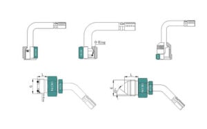
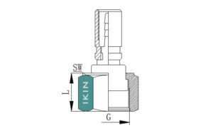
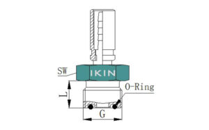
Most of the oil leakage faults in this part are the use of ordinary fine thread. For the joint body and the port of the machine, sufficient sealing work needs to be done. A combination of sealing gaskets or O-rings can achieve good results.

Second, the connection part between the joint body and the steel wire braided hose joint.

Among them, the connection link mainly uses the conical surface sealing or the end surface sealing, and the O-ring can also play an effective sealing role.

It should be noted that no matter what kind of sealing method is used, oil leakage problems may occur. 90% is due to failure of the pipe joint seal, and 10% is due to vibration or unqualified tightening torque.

II.Treatment strategy of hydraulic pipe joint oil leakage fault

Facing the common oil leakage of hydraulic connection adaptors, it is necessary to actively adopt scientific and effective methods to control and deal with them, to promote its maintenance of good operating conditions and support the stable operation of hydraulic connection adaptors.

1. Choose a reasonable way considering O-ring failure

O-rings play an important role in the sealing of hydraulic connection adaptors. When some failures occur, some oil leakage problems will be caused.We need to start from the actual failure performance of the O-ring seal, combined with the possible causes of the failure, and make targeted solutions to achieve good results.

First, the small leakage phenomenon. The main reason for this problem is that the installation process has been damaged; the compression is not enough; the friction surface is relatively rough; the groove size is not suitable enough; there is a side unloading situation, and so on.

To effectively improve these problems, reasonable measures need to be adopted, such as: (1) The installation process must be carried out in strict accordance with the established specifications and hydraulic pipe joint standards to ensure that the installation effect reaches the established goals;(2) Choose a suitable sealing method and appropriately increase a certain amount of compression;(3) Carry out a comprehensive and detailed inspection of the groove surface, focusing on observing the width and depth of the groove to see if it meets the corresponding standards, and also observe whether the groove surface and the joint are matched;(4) Check with side unloading and eccentricity.

Second, the big leak. This is mainly because the actual use effect of O-rings is not good enough, There are some quality problems, including use failure, serious scratches, deterioration, uneven expansion, scrap O-rings, etc.In order to effectively improve this problem, it is necessary to replace the new sealing ring in time to ensure the sealing effect.

Third, there is too much friction. The main problem of hydraulic connection adaptors causing oil leakage is excessive friction.The main reason is that the seal compression and swelling are too large, and there is contact between metal and metal.

Effectively find a good response strategy, effectively select the seal to achieve a good fit effect, ensure that there is good compatibility between the materials, observe whether the corresponding retaining ring is required during the operation of the sealing ring, and observe whether there is no problem of excessive uneven expansion.

Fourth,  leakage at low temperatures. The amount of compression is insufficient or the material of the O-ring is not suitable enough.In view of this situation, it is necessary to select a suitable sealing ring in time, appropriately increase the amount of compression, and promote it to provide a certain guarantee for thermodynamic contraction.

Fifth, early failure. When the O-ring is actually used,If the assembly process is damaged, there is a large amount of compression,  the selected O-ring size is not correct enough, or the design groove effect is not good, then it will cause abnormal operation of the O-ring and premature failure. As a result, it will not be able to exert its proper sealing function, leading to some oil leakage failures.In response to this situation, it is necessary to actively adopt scientific and reasonable methods to deal with .

For example, the installation process is implemented in accordance with the regulations, and the specific compression amount is controlled to ensure that it has a high degree of rationality.At the same time, appropriately increase the cross-section of the O-ring and check whether the O-ring is overused.

2. Correctly select and install the O-ring

O-ring occupies an important position in the sealing work of hydraulic connection adaptors,In order to effectively improve the sealing effect of hydraulic equipment and reduce the problem of oil leakage,It is necessary to effectively use a good O-ring, choose the right and appropriate method, and install it in strict accordance with the regulations.

First, it is necessary to effectively use a good O-ring, choose the right and appropriate method, and install it in strict accordance with the regulations.

On the one hand, the groove can be stretched to a certain extent after the O-ring is installed, the joint should be well contracted after being assembled.It can be seen from previous installation experience that the cross-sectional diameter of the O-ring needs to be 0.6 to 0.9 times the width of the sealing groove.

Secondly, scientifically and standardly implement installation operations.

The actual installation effect of the O-ring will have an important impact on its service life and the actual operating effect of the hydraulic connection adapters.Therefore, it is necessary to control the actual installation operation, and reasonably control the operation of the seal ring and the seal, so that it can achieve a good match in the groove.

In most cases, installation in the manner of rectangular grooves can achieve good results. At the same time, it should be noted that the actual processing, assembly and acceptance of the sealing groove are in progress.The fillet radius of the groove edge needs to be controlled above 0.2 mm, and appropriate assembly tools should be selected to reduce the occurrence of poor connection effects of the firmware.Ensure that the sealing ring is installed in place to meet the established sealing compression requirements.

三. Conclusion

Hydraulic connection adaptors are important in the actual operation of hydraulic equipment. They are also the main parts that are prone to some oil leakage failures. They will affect the operation of the entire equipment and need to be controlled in a reasonable way.

In hydraulic connection adaptors, O-ring is one of the key parts. It is necessary to choose a reasonable method based on its failure performance, and correctly select and install the O-ring.

hydraulic equipment supplier            hydraulic fittings hose coupling              hose fitting   hydraulic test kit               hydraulic test point                  hydraulic quick coupler                   pressure test point                      hydraulic coupling hydraulic test port                           pressure gauge adaptor                       hydraulic hoses test point   hydraulic test fittings               parker hydraulic test fittings    hydraulic test ports         hydraulic test hoses             hydraulic equipment corporation pressure gauge fittings            test points pressure gauge connection                hydraulic fluid test point             parker fittings                 connecting threads test point                  hydraulic test port fittings                     hydraulic coupling and hose          mini hydraulic presses shock valves              press valves flange valve            test point              fluid hydraulics           fluid connectors            hydraulic quick disconnect fittings             flange manufacturer              fluid power solutions             pressure couplings              fluid coupler               hydraulic flanges                       hydraulic pressure test

What is the base work of preventive maintenance in hydraulic system?

hydraulic tubular check valve manufaccturer in China

What is the base work of preventive maintenance in hydraulic system?

The hydraulic system is widely used in processing equipment due to its unique advantages. A large number of hydraulic control components and hydraulic actuators are distributed in the processing and rolling equipment, and they play a vital role in the precision control and transmission control of the equipment.

However, the stability of the hydraulic system also directly affects the stability of the overall equipment, production efficiency, product quality and maintenance costs.To further regulate the hydraulic system maintenance and management should be based on scientific, standardized, data and information to perform routine maintenance and management of the hydraulic system.

Following is the basic work of preventive maintenance of hydraulic system.

(一) Hydraulic system point inspection

All hydraulic systems should be included in the daily point inspection management of the equipment. The hydraulic system point inspection items should cover the following 4 elements: “liquid level, pressure, temperature, vibration”.

From power components, control components, executive components to auxiliary components, all should be included in the inspection scope.The frequency of specific inspections can be determined according to the working conditions and strictly included in the maintenance procedures of each machine train.

The point inspection data is uniformly recorded in the informationized equipment management system, which is convenient for closed-loop management and control of abnormal problems and subsequent data query and analysis.

1. Inspection of liquid level points

All hydraulic system oil tanks shall have level control standards. The minimum liquid level of the hydraulic system oil tank shall not be lower than 50% of the actual height of the oil tank, and the maximum liquid level shall not be higher than 80% of the actual height of the oil tank.

In addition to checking the liquid level, record the relevant data and deal with the liquid level fluctuations compared to the previous time and within 24 hours.

2. Inspection of pressure points

Machine train equipment should be based on the hydraulic control schematic diagram, establish a hydraulic system “pressure list” and incorporate it into periodic control.

The “list of pressure values” shall cover the rated pressure of the hydraulic system, working pressure, working pressure of each control point, and pressure values of relevant relief valves.

And according to the equipment working conditions, the above-mentioned “pressure point inspection” work is reasonably divided to different positions of personnel who perform the inspection work.

3. Inspection of temperature points

The hydraulic system of the machine train equipment should establish a “temperature list” and include it in the daily inspection and control. The “temperature list” should cover key hydraulic components and parts.

According to the working conditions of the equipment, each machine train classifies the work of “temperature point inspection”, divides the frequency, and reasonably divides the work to the personnel of different positions who perform the inspection work.

4. Vibration point inspection

Vibration of the hydraulic system pipeline should be paid attention to during the point inspection. When the hydraulic system is running, except for the vibration of the hose, all hard pipes should not have visible vibration.

5. Dynamic monitoring system

For key parts, an equipment dynamic monitoring system with intelligent monitoring and analysis can be introduced, such as real-time monitoring of the temperature and vibration of the pump body.

(二)Preventive maintenance

In the work machine equipment maintenance procedures, a special “hydraulic system preventive maintenance list” should be formulated, which covers the performance inspection and maintenance of the main components of the hydraulic system, the maintenance of the cleaning filter system, the check of the pressure value of the pump and valve, the maintenance of the seal and the leakage Troubleshoot and check tightness of pipe clamps and pipe joints.

The preventive maintenance methods for the four major components of the hydraulic system are as follows:

1. Power components

As the power component of the hydraulic system, the hydraulic pump should be tested and maintained regularly.

2. Control components

Hydraulic system control components mainly perform preventive maintenance for pressure valves and flow valves. Regular pressure reducing valves, relief valves, and throttle valves should be tested once per year for the pressure regulation and throttling performance of the valves. The above-mentioned valve parts in key parts should be tested every six months.

3. operating units

The preventive maintenance of hydraulic cylinders and hydraulic motor actuators is mainly for the inspection of piston rod wear and deformation, and regular inspection or replacement of seals.In principle, the seals of hydraulic cylinders should be disassembled and inspected every 5 years, and replaced or continued to be used according to the inspection conditions.

4. Auxiliary components
(1) Fuel tank

All oil tanks of high-pressure servo hydraulic system should be cleaned at least once a year, and all oil tanks of low-pressure auxiliary hydraulic system should be cleaned once every two years.The inside of all hydraulic system oil tanks should be separated from the oil suction side and the oil return side according to the design standards, and the height of the pump suction port from the bottom of the oil tank should not be less than twice the diameter of the suction port pipe.

(2) Filter

All hydraulic systems should use filters with differential pressure indicators, and perform filter replacement and maintenance work based on the alarm conditions of the differential pressure indicators. The differential pressure indicators should be checked every six months.

The filtration accuracy of the filter element at the outlet of the pump should not be less than 7μm, and the filtration accuracy of the circulating filter system of the pump station should not be less than 5μm.

(3) Plate cooler

The heat exchange effect of the plate cooler should be checked once a month, and the execution records and data comparison of the temperature of the cooling water in and out, and the temperature of the in and out oil should be integrated. According to the data chain comparison and the cooling effect in the same season of the previous year, the plate cooler shall be disassembled and maintained.

In principle, the plate cooler should be disassembled and maintained at least once every three years.Periodic inspection and cleaning of Y-type filters of all plate cooler inlet pipes should be finished per quarter.

(4) Pipeline

The pipeline maintenance work of the hydraulic system is mainly carried out for pipe joint inspection, pipe clamp tightening inspection, hose inspection and so on.

All pipe joints and pipe clamps shall be classified and regularly tightened inspection according to the distribution of valve stations and equipment working conditions. The longest period of tightening inspection shall not exceed 1 time/quarter.The fastening of pipe joints and pipe clamps should be based on the “131” principle, that is, focus on the control of a line above the strip, within 3 meters of the execution end, and a power source output end.

The visual inspection of the hose should be carried out once per month, which can be carried out in conjunction with the periodic short-term regular inspection of the equipment.

5. Accumulator

All accumulators shall perform periodic inspection of airbag pressure, and the inspection cycle is once per quarter. The air bag inflation pressure is 70% to 75% of the working pressure of the control oil circuit of the accumulator.

(三)Leakage control of hydraulic system

  1. The machine train equipment should establish a standardized leakage control ledger, and the ledger information should cover the specific leakage location, leakage degree, approximate leakage volume, leakage point seal parameters and other information.

2. The machine train equipment should establish a list of common and key control leak points, and form a leak detection operation guide to guide the operators and electric clamp maintenance personnel to perform the hydraulic system leak detection work.

3. The electric fitters who    perform the leakage treatment of the hydraulic system shall be trained to perform the norms.

 4. For the preventive maintenance of leaks, a dedicated person should be designated to be responsible for the closed-loop management and control of standardized operations and problems.

5. For the 5S management of hydraulic system leakage, a division of responsibility system can be adopted, such as the system of appointing people and points.

 6. If the hydraulic system leakage management and control of the current month fails to achieve the control target, a relevant leakage analysis meeting should be organized and the meeting minutes should be formed; the person in charge and the completion time of the problem improvement item should be clarified, and closed-loop control and follow-up assessment should be implemented.

hydraulic hoses              test point            hydraulic test fittings              parker hydraulic test fittings           hydraulic test ports             hydraulic test hoses               hydraulic equipment corporation                 pressure gauge fittings                 test points              pressure gauge connection             hydraulic fluid test point                parker fittings              connecting threads test point            hydraulic test port fittings           hydraulic coupling and hose           mini hydraulic presses           shock valves          press valves          flange valve          test point        fluid hydraulics         fluid connectors           hydraulic quick disconnect fittings         flange manufacturer        fluid power solutions            pressure couplings              fluid coupler            hydraulic flanges                hydraulic pressure test      hydraulic equipment supplier            hydraulic fittings hose coupling                hose fitting             hydraulic test kit                     hydraulic test point                              hydraulic quick coupler              pressure test point              hydraulic coupling               hydraulic test port                    pressure gauge adaptor


What is the Reliability of conventional hydraulic systems?

TP Direct Pressure Gauge Connector for Hydraulic manufaccturer in China

What is the Reliability of conventional hydraulic systems?

Hydraulic system has the advantages of high power, small size, light weight, fast response, high precision and high rigidity against load. Therefore, it has been widely used in many important fields such as metallurgical industry, construction machinery, aerospace, shipbuilding and so on. Hydraulic systems are often at the core of control and power transmission in various equipment and systems.Therefore, it is necessary to study the reliability of the hydraulic system.

The conventional reliability research of hydraulic system is as follows:

1. Reliability design

The reliability design of the hydraulic system is the most important part of the hydraulic reliability engineering. The concept of “reliability is by design” has been recognized by people.The main reliability design methods of hydraulic systems include redundant design, energy-saving design, environment-resistant design and simplified design.

(1) Redundant design

Redundant design uses multiple systems, and when one of them has a problem, it will be removed or isolated through fault monitoring.

Redundant design can significantly improve the reliability of the system, so that it can continue to work in the event of a failure.It is generally used in places that require the system to be “absolutely” reliable, such as aerospace, nuclear power plants, large ground power stations, etc., to ensure the mission reliability of the system.

The disadvantage is that the implementation cost is high, the control model of the system is complicated, and there is a certain limit to the improvement of system reliability.The introduction of redundant units will inevitably cause additional costs. Besides it will increase manufacturing costs, use and maintenance costs.

(2) Energy-saving design

The use of new components and new technologies to realize the energy saving of the hydraulic system can reduce the installed power and failure rate.

If a new type of energy conversion element-hydraulic transformer is used, the hydraulic transformer can adjust the flow and pressure according to the load without loss. The application of hydraulic transformer to the hydraulic system not only brings about a significant reduction in the installed power of the system, but also opens up a new way for reducing system energy consumption and simplifying the structure of the hydraulic system.

(3) Environmentally resistant design

The hydraulic system that works in special environments such as the seabed, underwater, pollution, etc., must be designed for environmental resistance.

For example, conduct theoretical and practical research on the electro-hydraulic servo platform of the underwater oil storage and supply system, design a platform-type electro-hydraulic servo system that can adaptively adjust the hull posture. And do pioneering research work of anti-corrosion and seal the hydraulic components and systems in the marine environment.

(4) Simplified Design

The simplified design can improve the basic reliability of the product. The hydraulic system should use the integrated design of pumps, valves, and tanks as much as possible to reduce pipeline connections. Use unitized and modular design as much as possible to reduce the number of product components and their mutual connections.

As far as possible to achieve the standardization, serialization and generalization of parts and components, and strive to achieve multiple functions with fewer parts and components.

2. eliability prediction

Predicting the reliability of a system is an important parameter to measure the pros and cons of a system and whether it meets the task requirements, and it is also an important means of mutual evaluation between systems.

The reliability prediction of the hydraulic system can generally be predicted by the mathematical model method plus the correction coefficient.

3. Reliability analysis

(1) Fault tree analysis

Fault tree analysis technology is widely used, especially in the fields of nuclear industry, aerospace, machinery and electronics, weapons, ships, chemical industry, etc. It plays an important role in improving the safety and reliability of products.

Fault tree analysis is gradually applied and researched in the reliability, safety, and fault analysis and diagnosis of hydraulic systems. For example, the research on the hydraulic system of crane travel is proposed, and a method of qualitative analysis of the fault tree using the minimum cut-set matrix and the calculation of structural importance is proposed. The fault tree analysis of the hydraulic system of the main cylinder of the hydraulic press is carried out, and the improvement measures of the hydraulic system are proposed based on the analysis results.

(2) GO method

GO method is a success-oriented reliability analysis method. The GO method uses the GO graph to simulate the system, and the GO graph can directly calculate the system’s success probability. For systems with multiple states and timing, it can solve the reliability problems of complex systems that are incapable of fault tree methods. For example, the GO method is used to carry out qualitative analysis and quantitative calculation of the reliability of the hydraulic system of the loader, and the reliability of the hydraulic system is quantitatively evaluated.

4. summary

With the development of hydraulic systems in the direction of rapid, high-power, and high-precision, hydraulic systems and equipment have more and more functions, structures and information are becoming more and more complex, performance indicators are getting higher and higher, and the work intensity is getting heavier and heavier. The relationship is getting closer.

This situation has brought about two results. On the one hand, productivity and product quality have been improved; on the other hand, the probability of failure has also increased.

 Once the hydraulic system fails, it will cause heavy losses. Therefore, it is of great significance to study the reliability of the hydraulic system.

hydraulic test fittings             hydraulic pressure test fittings             hydraulic test hose                   hyd test fittings               hydraulic test port fittings                       cat hydraulic test fittings                        john deere hydraulic test fittings                     hydraulic test gauge fittings                   hydraulic test hose fittings                     hitachi hydraulic test fittings                       jcb hydraulic test fittings                       jic hydraulic test fittings                      hydraulic test fittings kit                 komatsu hydraulic test fittings                  metric hydraulic test fittings                       hydraulic test point fittings                  hydraulic test point connectors                      caterpillar hydraulic test port fittings                          parker hydraulic test port fittings                             parker hydraulic test fittings                    parker hydraulic test fittings                    stauff hydraulic test fittings                        hydraulic test tee fittings                     volvo hydraulic test fittings                        pressure test point                           hydraulic equipment supplier                       hydraulic fittings             hose coupling                hose fitting              hydraulic test kit               hydraulic test point                hydraulic quick coupler                 pressure test point                 hydraulic coupling 

How to eliminate mechanical vibration generated in hydraulic system?

hydraulic fittings of shuttle valve manufaccturer in China

How to eliminate mechanical vibration generated in hydraulic system?

Vibration is a phenomenon that often appear in the hydraulic system, which is mainly from two aspects: the mechanical vibration generated by the motion of the system, and the working fluid generated in the process.

Most hydraulic vibration systems are very harmful, of course, except for the use of hydraulic devices operating on the principle of vibration. The vibration adirectly affect the working performance of the hydraulic system, causing damage to the hydraulic components, and accessories line, thereby shortening the system service life.

一. Reasons for vibration of mechanical system

1. Unbalanced rotors

When the prime mover, hydraulic pump, hydraulic motor and so on rotate at high speed, if the shaft imbalance, it will have periodic unbalanced force. Thereby this mechanical vibration  will also cause a series of vibrations to integrated block or other pipelines when mounting base line.

2. Two-axis connection is not concentric

When the prime mover is connected to the hydraulic pump and the hydraulic motor to the load through the coupling, if the coupling is deviated or the rotating shaft is not strong due to the different axis of the connected part, vibration will occur.

3. Improper bearing clearance

During the installation process, if the bearing is selected improperly or the bearing clearance is adjusted improperly, it will cause mechanical vibration. At the same time, when the prime mover, hydraulic pump, and hydraulic motor are in operation, the increase in bearing clearance due to wear and the loosening of fasteners will also cause mechanical vibration.

二. Measures to eliminate mechanical vibration

  1. For the vibration caused by the unbalance of the rotating body, the prime mover, hydraulic pump and hydraulic motor can be selected as far as possible under the premise of meeting the requirements of use.
  1. For the vibration caused by the non-concentricity of the rotating shaft after installation, in addition to the reasonable design of the space installation structure of the connected parts and ensuring the quality of the parts, it is best to design a connected parts as a structure that can be adjusted in the spatial position of the rotating shaft. It will be convenient to adjust when facilitate installation, to ensure good concentricity.
  1. For the vibration caused by the improper bearing clearance, in addition to the selection of the bearing (high-precision bearings have high rotation accuracy, stable operation, and small vibration after equipment installation, but this will increase the manufacturing cost of the equipment, which needs to be considered). When designing the bearing support structure, choose a structure with a gap that is easy to adjust as much as possible.

三.Conclusion

Vibration is an inseparable physical phenomenon of the hydraulic system. Correctly analyzing the causes of vibration and taking reasonable and effective control measures are important to improve the efficiency of the system and extend the life of the system.

pressure gauge fittings                       pressure gauge connection                   hydraulic fluid test point                     connecting threads test point                           hydraulic test port fittings                     hydraulic fittings              hose coupling                        hose fitting                    hydraulic test kit                         hydraulic test point                        hydraulic quick coupler    hydraulic accessories                             pressure test point                           hydraulic equipment supplier     hydraulic coupling                 hydraulic test port                pressure gauge adaptor      hydraulic equipment corporation               valves flanges          fluid design products                    hydraulic flange fittings                bspp hydraulic fittings                     valve flanges                    quick disconnect couplings                  fluid valve,american fluid power                          quick connect couplings  

How to Inspect and maintain Hydraulic System?

hydraulic hose damping valve manufaccturer in China

How to Inspect and maintain Hydraulic System?

Hydraulic transmission is widely used in construction machinery because of its smooth and uniform motion transmission, small size, compact structure, sensitive response, simple operation, easy automation, automatic lubrication, high degree of standardization, and long life of components.

At the same time, there are also some shortcomings, such as high requirements for hydraulic oil, high price of hydraulic components, and difficulty in finding the cause of hydraulic equipment failure.

Therefore, once a failure occurs during use, it is difficult to accurately diagnose. Therefore, when the hydraulic system fails, the maintenance personnel are often at a loss, and often cause deformation and damage of the parts during the maintenance, and cause certain losses to the user.

1. Checking method of hydraulic system failure

  • Direct observation method

In diagnosing hydraulic system failures of construction machinery, the intuitive inspection method is the most convenient and easiest method, which is to check the parts by sniffing, hearing, touching, and seeing to make some simple fault judgments.

The visual inspection method is feasible when the machine is working and not working. Although the visual inspection method is relatively simple, it is a very feasible method. As long as accumulated experience for a long time, the inspection process will be more handy.

  • Operation adjustment inspection method

The operation adjustment inspection method refers to operations taken under load and no-load operation. By comparing with the previous work conditions, faults can be found faster and more accurately.

In the inspection process, it is first necessary to perform an operation under no-load conditions, and ensure the normal operation of all hydraulic systems, so that abnormal places are exposed. Then operate under load conditions.

The operation method must be fully combined with the adjustment method in the process of checking the fault. The adjustment process refers to adjusting the adjustable parts such as the stroke, flow and pressure of the hydraulic system and the fault-related components to find the cause of the fault.

  • Contrast replacement inspection method

If there is no test instrument when checking the hydraulic system failure, then the contrast replacement inspection method is a very effective method.

 However, when the comparative replacement inspection method is used to check the failure of the hydraulic system, the operation process is very complicated due to inconvenient dis-assembly, many components, and structural limitations.

Compared with the one-way valve, overflow valve, balance valve and other easy-to-disassemble, small-volume components, using this method is very convenient. In the process of using the contrast replacement inspection method, you must pay attention to the correct connection, and can not cause damage to other surrounding components, so as to ensure the correctness of the fault judgment.

  • Instrument measurement inspection method

When detecting the failure of the hydraulic system, the instrument measurement inspection method is the most accurate method. The fault judgment is made by measuring the oil temperature, flow, pressure, etc. Among them, measuring pressure is relatively common, and the flow rate can be roughly judged by the execution speed of the component.

Under normal circumstances, select several key points in the entire hydraulic system, measure the pressure of the hydraulic system, and then compare the data on the system diagram to judge the condition of the oil circuit before and after the measured point.

2. Maintenance of hydraulic system

Correct maintenance is the foundation of the reliable operation of the hydraulic system. According to work practice, the maintenance of the hydraulic system of construction machinery should do the following.

  • Hydraulic oil

The hydraulic oil plays the role of transmitting pressure, lubricating, cooling, and sealing. The hydraulic oil should be selected according to the brand specified in the “Instruction Manual”. Under special circumstances, the substitute oil should meet the same performance as the original brand, and hydraulic oils of different brands cannot be mixed. Inappropriate selection of hydraulic oil is the main reason for the early failure of the hydraulic system and the decline in durability.

  • Regular maintenance

At present, some hydraulic systems are equipped with smart devices, but their monitoring range and accuracy have certain limitations. Regular inspection and maintenance of the hydraulic system is still essential. Therefore, the inspection and maintenance of the hydraulic system requires the monitoring of the smart device combined with regular inspections.

  • Prevent the invasion of particulate impurities

Pure hydraulic oil is the life of the hydraulic system. If the hydraulic oil is mixed with solid impurities, it will cause strains on the precision parts, jams, blockage of the oil passage, etc., which may even endanger the safe operation of the hydraulic system.

To prevent the mixing of solid impurities, pay attention to the following points: When refueling, the hydraulic oil must be filtered, and the refueling tools should be clean and tidy. The filter at the filler port of the hydraulic oil tank cannot be removed in order to increase the fueling speed.

  • Prevent the intrusion of fluids such as water and gas。

Excessive water in hydraulic oil will rust the hydraulic components, emulsify the oil, reduce the strength of the lubricating oil film, and accelerate mechanical wear. Therefore, not only to prevent moisture intrusion during maintenance, but also to tighten the lid when the oil storage barrel is not in use, best to put it upside down.

3. Conclusion

For the pollution and leakage of the hydraulic system of construction machinery, analyze and explore the root causes of the failure, understand the factors that cause the failure, and recognize the hazards. Pay attention to use problems and preventive measures, correctly select hydraulic oil according to the basic requirements, and use and maintain it reasonably, which can effectively improve the working performance, efficiency, economy, reliability and service life of hydraulic equipment.

JIC test point                       hydraulic test tee fittings             hydraulic test connector                    hydraulic equipment supplier                   hydraulic fittings                    hose coupling                    hose fitting                   hydraulic test kit                 hydraulic test point                hydraulic quick coupler                    pressure test point                         hydraulic coupling                          hydraulic test port                   pressure gauge adaptor              standard hydraulic fittings               Manufacturer for hydraulic fittings                   Hydraulic Accessories                          HYDRAULIC TEST POINT COUPLING                          hydraulic equipment corporation                         pressure gauge fittings                       pressure gauge connection                   hydraulic fluid test point                     connecting threads test point                           hydraulic test port fittings


How to analysis on the generation and elimination of vibration in fluid hydraulic system?

TB Hydraulic Test Coupling with Tube

How to analysis on the generation and elimination of vibration in fluid hydraulic system?

Vibration is a phenomenon that often occurs in the working of hydraulic systems. It mainly comes from two aspects: the vibration generated by the movement of the mechanical system and generated during the working process of the fluid.

Most of the vibrations are very harmful to the hydraulic system, of course except for the hydraulic equipment that uses the principle of vibration.

Vibration directly affects the performance of the main engine and the hydraulic system, causing damage to the hydraulic components, accessories and pipelines. Then thereby it will shorten the system service life.

1. Causes of fluid vibration

  • Vibration of hydraulic pump

The flow pulsation of a hydraulic pump is an inherent characteristic of the pump. During the process of sucking and pressing oil, the pressure and flow periodically change will form a pressure pulse.

This pulsation will inevitably cause pressure pulsation in the outlet pipe of the hydraulic pump and spread to the entire system, produce fluid vibration. In addition, the pressure shock in the trapped area of the hydraulic pump, the back flow of the plunger pump, and the inability of the variable pump to reduce the oil delivery in time when the oil pressure rises, all will cause hydraulic vibration.

  • Vibration caused by bubbles

The oil is generally mixed with about 2% to 5% of air, and the mixed air is suspended in the hydraulic oil in the form of bubbles with a diameter of 0.05 to 0.5 mm.

When the partial pressure of the oil mixed with air drops to the air separation pressure, the dissolved air in the oil will separate and precipitate, forming a large number of bubbles (this phenomenon is called cavitation).

When the oil with a large number of bubbles flows again to a higher pressure at high places, the bubbles are instantly crushed to form local high pressures, causing large pressure fluctuations and causing the system to vibrate.

  • Vibration caused by hydraulic valve switching

In the hydraulic system, when the load inertia is large, if the directional control valve is suddenly closed or opened, the flow rate of the liquid flowing in the pipeline will change suddenly. At this moment, the conversion of the kinetic energy of the liquid will cause pressure shock and cause vibration.

  • Forward rush phenomenon and vibration caused by impact load

When the load change causes the hydraulic actuator to suddenly change from the working state to the unloaded state, due to the inertia of the system, a forward thrust will occur, causing hydraulic shock and vibration.  When the hydraulic actuator is suddenly loaded from the no-load state, due to the shock load causes the liquid pressure to rise suddenly, causing pressure shock and vibration.

2. Measures to eliminate fluid vibration

  1. Reduce the influence of air bubbles
  • Reasonable selection of hydraulic components will help reduce the influence of air bubbles on the system

When selecting an oil suction filter, you can choose an out-of-box self-sealing oil suction filter with a signaling device, such as the TF series out-of-box self-sealing oil suction filter. When the filter element is blocked by contaminants, the vacuum degree of the oil outlet is 0.018, then the transmitter will send out an alarm signal to remind the operator to replace the filter element in time to avoid clogging of the filter element. Or it will result in poor oil suction of the oil pump and partial vacuum at the oil inlet and air suction.

  • Reasonably design the structure of hydraulic components to help reduce the influence of air bubbles in the system

Set up pressure measuring joints with exhaust devices at each high point of the hydraulic pipeline, and regularly discharge the gas mixed into the pipeline through the exhaust device of the pressure measuring joints.

When designing the oil tank, set the oil filter and the oil suction filter respectively arranged at both ends of the oil tank to increase the stroke of the oil flowing in the oil tank, so that the oil has as much time as possible to precipitate bubbles during the bypass process.

The pipeline connection is well sealed , Choose a combined sealing gasket with better sealing performance at the junction of the pipe joint and the integrated block to avoid air infiltration.

2. Reduce the impact of hydraulic valves

The reversing valve and the overflow valve in the hydraulic valve are easy to cause fluid impact, and then cause vibration. So this point should be considered when selecting the model.

Selecting the directional valve, when the pressure is high and the flow is large, choose the elector-hydraulic directional valve with better commutation stability. When selecting the directional valve’s neutral function, if the load inertia is large, you can choose Y type Function to ensure that there is still a certain buffer effect after the valve is closed. If the hydraulic motor of the large inertia system is not allowed to continue to rotate after the reversing valve being closed, you can choose the O-type or M-type function.

And before the reversing valve is closed, it is best to first unload the hydraulic pump and close the reversing valve after a certain delay. If select the overflow valve, when the pressure is high and the flow is large, use the pilot-operated overflow valve.

3. Appropriate dynamic compensation

If an overload supplement valve and a back pressure valve are installed in the system, the dynamic performance of the system will be greatly improved and hydraulic shock will be reduced.

In addition, setting a back pressure valve can also increase the minimum working pressure of the system, avoid the generation of bubbles. And at the same time it will slow down the front-shooting phenomenon caused by changes in working conditions, thereby reducing system vibration.

4. Other measures

In order to reduce pipeline vibration, when designing hydraulic pipelines, pipe clamps can be installed according to the design specifications and sharp turns of the pipeline should be avoided as much as possible.

Accumulators should be installed at the inlet and outlet of hydraulic actuators to relieve hydraulic shock.

3. Conclusion

Vibration is an inseparable physical phenomenon of the hydraulic system. Correctly analyzing the causes of vibration and taking reasonable and effective control measures are important to improve the efficiency of the system and extend the life of the system.

 pressure test point                           hydraulic equipment supplier                       hydraulic fittings             hose coupling                hose fitting              hydraulic test kit               hydraulic test point                hydraulic quick coupler                 pressure test point                 hydraulic coupling                 hydraulic test port                pressure gauge adaptor                    hydraulic equipment supplier                    hydraulic fittings              hose coupling                        hose fitting                    hydraulic test kit                         hydraulic test point                        hydraulic quick coupler   

Is test point adaptor necessary for hydraulic system?

Test Coupling with Male Cone DKO-24° manufaccturer in China

Is test point adaptor necessary for hydraulic system?

The hydraulic system is very complicated.

During the flow of hydraulic oil, the erratic flow direction and flow rate of the liquid are difficult to predict, especially for the long distance.

For such a complex hydraulic system, the system is difficult to debug and maintenance is inconvenient.

Therefore, this feature should be fully considered in the design process, and various possible means should be used as much as possible to improve and enhance the performance of the system.

The application of pressure test point in the hydraulic system is helpful to the debugging of the system. And it can improve the working performance of the system.

HYDRAULIC test point manufacturer

1. The application of pressure test point is helpful for system fault diagnosis

The hydraulic system inevitably has various faults during the working process, and the reasons for the faults are often very complicated. The abnormal working of the hydraulic motor is one of these complicated faults.

The reason for the abnormal working operation of the hydraulic motor is complicated. It can be caused by the blockage of the hydraulic or hydraulic pipeline, or it may be caused by the failure of the load or the hydraulic motor itself.

Once a failure occurs, quickly identifying the cause of the failure is the key to troubleshooting.

Install a pressure test point at the oil inlet of the hydraulic motor, it will help judge the possible cause by testing the pressure of the oil inlet of the hydraulic motor.

It will be very beneficial to find out the cause of the fault and even quickly eliminate the fault.

2. The application of pressure test point is helpful to the adjustment of system pressure.

 In the conventional design, the oil pump outlet of the hydraulic system is equipped with a pressure gauge.

The pressure gauge is not only a measuring tool for adjusting the maximum working pressure of the oil pump outlet, but also a monitoring tool for the working pressure of the hydraulic system.

 Due to the special characteristics of the hydraulic pipeline system such as long oil flow distance, liquid flow direction and flow rate change in the middle, the actual working pressure of the hydraulic motor and the outlet pressure of the oil pump may be far apart.

Through the oil pump outlet pressure gauge it is difficult to debug the actual working pressure of the hydraulic motor and the detection of the working pressure of the hydraulic motor, so the pressure adjustment when the hydraulic motor is working becomes very difficult.

And at the same time, it is impossible to make the hydraulic motor work under the appropriate pressure, which will inevitably affect the working performance of the hydraulic system  and the working state of the hydraulic motor.

 If a pressure gauge is installed directly at the oil inlet of the hydraulic motor, although the working pressure of the hydraulic motor can be measured, it will increase the cost of the hydraulic system. Moreover, the choice of the installation position of the pressure gauge, as well as the working environment and service life are all difficult to guarantee. If a pressure test point is installed at the oil inlet of a hydraulic motor, the situation is different.

Since the pressure test point is very close to the hydraulic motor, the pressure measured basically reflects the working pressure of the hydraulic motor, which will help the accurate adjustment of the working pressure of the hydraulic motor. At the same time, the cost of the pressure test point is relatively low, the installation location is easy to choose, it is not restricted by the working environment, and the service life is long.It can completely avoid the various problems of installing the pressure gauge at the oil inlet of the hydraulic motor.

3. The application of pressure test point helps to improve the working performance of the system

Hydraulic shock is inevitable in the process of hydraulic work, and hydraulic shock is very harmful to the normal operation of the hydraulic system. Avoiding or reducing hydraulic shock as much as possible is a problem that must be considered in the hydraulic system design process.

There are many reasons for the hydraulic shock, including the sudden change of the liquid flow direction and the mixing of air bubbles in the hydraulic oil. Then we can fix the pipe by using the hydraulic pipe clamp to avoid severe vibration, and set the air bubble filter metal mesh in the oil tank. And by extending the distance of the liquid flowing in the tank to make the bubbles gradually seep out, try to avoid the sudden change of the liquid flow direction.

Therefore, it is a good choice to install a pressure test point in the hydraulic pipeline. The pressure test point can be used to release the gas gathered in the higher part of the hydraulic pipeline, so as to compensate for the low rate of bubble leakage in the oil tank and reduce hydraulic shock. It is very beneficial to improve the working performance of the system.

In summary, the proper application of pressure test point in hydraulic systems generally has more advantages than disadvantages. It is very useful for fault diagnosis, debugging and performance improvement of hydraulic systems.

What is the function of test point in hydraulic system?

hydraulic Test coupling/bigger flow rate

hydraulic test Point supplier

Top 3 Manufacturer in China

SGS Approved

What is the function of test point in hydraulic system?

In order to simplify machinery structure design, the driving systems of modern machines commonly are driven by full hydraulic systems. 

The features of full hydraulic system include reasonable overall layout, simple structure design, convenient system operation, reliable quality, strong driving power and convenient maintenance and commission.

It becomes more and more popular among users.

we manufacture hydraulic test point&hose

In order to understand the working situations of full hydraulic system comprehensively, the pressure testing points are set in the design of full hydraulic system, and pressure taps are equipped as well in the pressure testing points to measure whether the pressure in the oil way is within normal range or not, so as that the pressure can be measured quickly for troubleshooting.    

Ikin test point in hydraulic valve

I. The working principle and application of pressure test point

1. There is a self-sealing valve in the pressure test point. Due to the function of spring, it would be closed when used separately.

And it would be opened when it is connected with the measuring hose tube or pressure test point with same thimble to take samples and system pressure testing in the high-pressure or low-pressure fluid system.

The working pressure can reach 63Mpa, and pressure of BP can reach 250Mpa.

the video shows how Ikin hydraulic test point works

2. The pressure test point is mainly used in the full hydraulic tubing system for pressure supervision detection, gas discharging, samples taking in the high-pressure and low-pressure systems.

It is widely used in the engineering machinery, agricultural machinery, hydraulic system, testing equipment and so on.

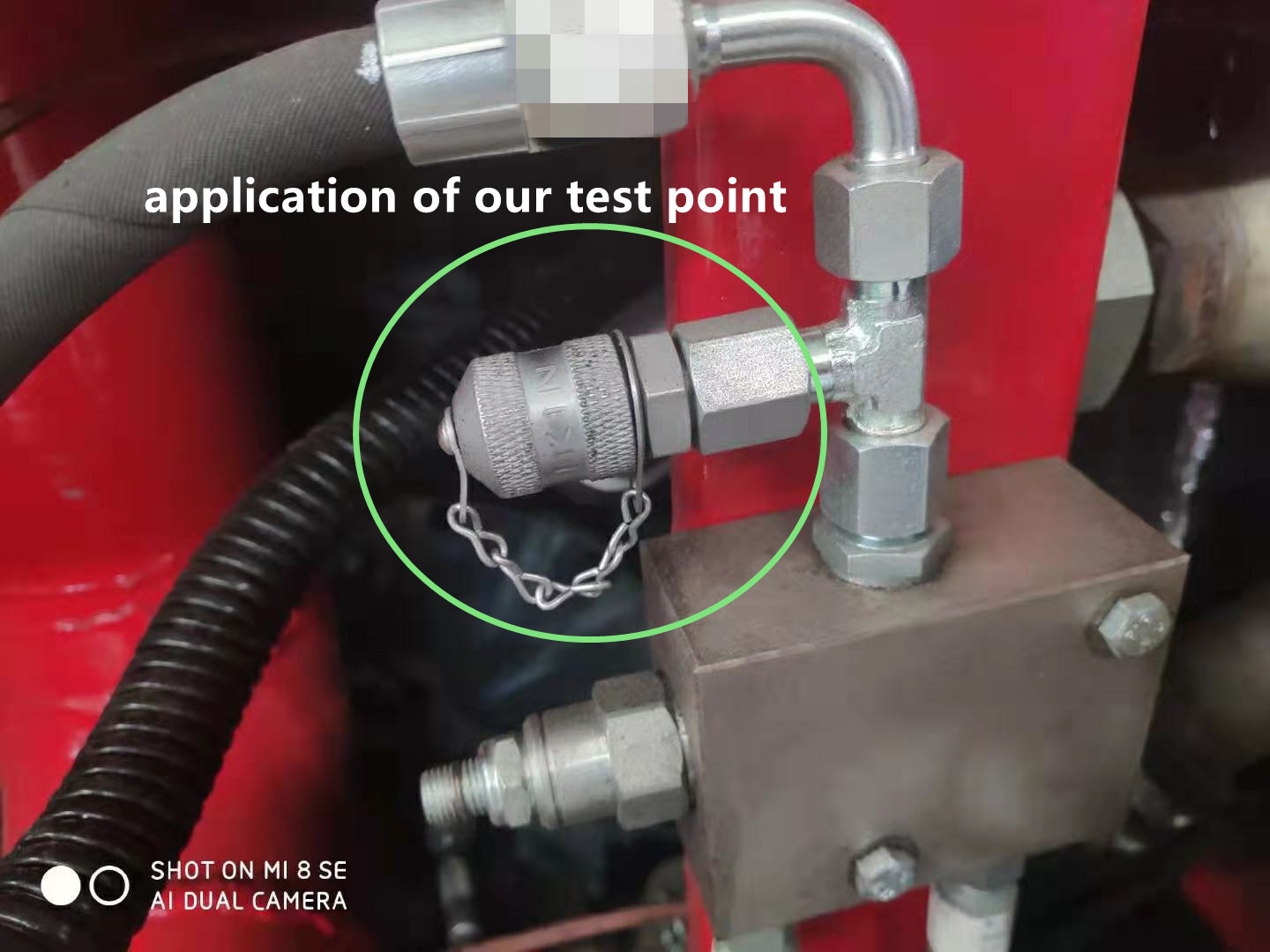
For example, the hydraulic system and operating of hydraulic excavator are complicated, but how to judge hydraulic failures?

Shown as the below picture, pressure test point is needed now to measure the hydraulic pressure of testing point so as to find the root of the problem.


parker fittings replacement supplier

The pressure tap can bear pressure testing in the hydraulic system, which is critical significant for stable hydraulic equipment and reliable operation.

Therefore, pressure test point is widely used as standard configuration in current hydraulic systems.

II. The necessity of setting Hydraulic testings

The whole moving system driven by hydraulic system is integrated by hydraulic motor, hydraulic action component, hydraulic valve, oil pipes and others. It is very complicated.

The pipe line from oil pump to hydraulic action components is long, as well as the hydraulic flowing distance. It is hard to predict press loss as fluid flowing direction and flowing speed changes.


IKIN FLUID pressure test point

It is difficult for system commission and inconvenient for maintenance.

As a result, the features of full hydraulic system should be taken into full consideration in the design. Pressure testing points should be set and hydraulic testing should be equipped.

Meanwhile, the cost of hydraulic testing is low, installation location is flexible, and it is not limited by working environment with long usage life.

It is benefit for hydraulic system commission and working performance of hydraulic system could be improved.

III. Convenient for failures diagnosis in full hydraulic system

The full hydraulic system is complicated, and number of hydraulic motors and integrated valve blocks are many, leading the probability of failures is high. Once failures happen, finding the reasons of failures quickly is the key in troubleshooting.

Installing hydraulic testing in full hydraulic system can analyze the reasons that may happen through pressure testing in all pressure points.

With the help of hydraulic testing to analyze potential reasons for failures in full hydraulic system, it is very good at troubleshooting and finding out reasons for failures.

IKIN hydraulic pressure test point

IV. Improve the working performance of full hydraulic system​

The number of pumps and motors in full hydraulic system is many, and flow capacity of oil is high. Due to the limitation of machinery structure, the flowing distance of hydraulic oil in the oil box is short, bubble exudation rate is low, and huge amounts of bubbles would be brought into pipeline again.

Hydraulic test point installed in hydraulic pipeline can be used to release gas in higher parts that are gathered in the hydraulic pipeline so as to make compensation for the shortage of low bubble exudation, which is very beneficial for decreasing hydraulic impacts and improving working performance of system.

IKIN FLUID pressure test coupling

V. Conclusion

The number of hydraulic components and action parts is many in the full hydraulic system, and system is complicated.

Machinery structure, working environment, special demands and various issues that may happen should be taken into full account when design full hydraulic system equipment.

It is very necessary to adopt various methods comprehensively to improve working performance and maintainability.

Generally speaking, in the improving the reliability of quality, the advantages of proper adapting hydraulic testing in full hydraulic system equipment are more than disadvantages, which are also very beneficial for commission and performance improvement in full hydraulic system.

What we supply?

—— Top 3 manufacturer in China

Benefits You Can Find In Ikin

factory Price and low moq

reliable quality, supplier for Eaton, Hawee and so on

100% leakage Inspection Before finished

3 years warranty

10 working days for bulk shipping

match other fittings like minimess, stauff and so on

cone seal design structure, stable and long life

Get Your Free Sample

in 2 days

*We respect your confidentiality and all information are protected.

What is the common leakage problems and possible causes of Hydraulic Testings?

Tee Hydraulic Test Coupling manufacturer in China

What is the common leakage problems and possible causes of Hydraulic Testings?

As an important tool for pressure testing and sampling in hydraulic systems, hydraulic test point are widely used.

However, establishing a reliable and leak-free connection should be the primary goal of any hydraulic system.

There are many different kinds of hydraulic testings on the market can be selected. No matter which type , it will bring inconvenience and trouble to the entire system when leaked.

Common leakage problems and possible causes of hydraulic testings:

1. When the oil leaks from the inlet end, possible reasons for this region leaks as follows:

IKIN FLUID hydraulic test point
①O-ring/sealing ring is damaged or missing (For O-ring joint / seal ring)

The unreasonable design of the sealing ring and the sealing groove will cause the compression of the sealing ring to be too large or too small; if it is frequently disassembled, the surface of the sealing ring may be worn, slag and not pressed tightly.

When the use time is too long to exceed the shelf life, the ring loses its sealing, elasticity, deformation and cracks, etc., so it is easy to leak.

② The size of the connecting thread of the joint body is poor

The connecting thread of hydraulic testings is selected according to the thread of the oil port end.

The external thread connection length of hydraulic testings should be less than the full thread depth of the internal thread of the oil port end. Otherwise, the thread of the column end will not be screwed to the bottom, resulting in leakage of the threaded end.

③ The oil port end is damaged

Scratches on the sealing surface of the O-ring at the port end will prevent the O-ring from effectively sealing, resulting in leakage; the edge of the O-ring sealing surface is too sharp or burrs, and it is easy to cut the O-ring during installation and cause leakage;

④ Improper torque / improper assembly

After torque assembly, make sure that the end face of the joint seal is in full contact with the end face of the oil port. If there is a slight gap, the O-ring is likely to be squeezed out during the system’s long-term pressurization process, resulting in leakage.

IKIN hydrauic test point, 100% leakage testing before package.

IKIN FLUID-leakage testing

2. Leakage in the center of the spool. The possible causes of leakage in this area are as follows:

IKIN FLUID hydraulic test
① Excessive pressure

According to the international standard ISO 15171-2, the maximum working pressure of hydraulic testings is 63Mpa (630bar). If the system pressure is too high (the maximum pressure exceeds the limit), the valve core will be damaged by a huge impact, which will cause hydraulic testings to leak.

② Damage of internal seal

When impurities enter the hydraulic system and the pressure is tested, these impurities will damage the internal seals of hydraulic testings, and will also affect the service life of the entire hydraulic system.

IKIN FLUID is manufacturer in China, specizlize in test fittings, 100% leakage testing before package

ODM/OEM/customized accepted.

click the below links to get more specification

3. Leakage caused by cracks. The possible reasons for leakage in this area are as follows:

IKIN FLUID hydraulic test
① The wall thickness is too thin

When the design wall thickness of some parts of the hydraulic test point joint is too thin, and there is stress concentration, the thin-walled part will be broken or cracks will cause leakage.

② Inferior quality materials

Choosing low-quality materials may cause small cracks in the joint body, but these cracks will be difficult to find after electroplating.

Therefore, hydraulic testings body will expand and crack under the constant pressure of the system, resulting in leakage.

Conclusion

The above is a summary of hydraulic testings in the hydraulic system application practice, and several reasons are prone to leakage.

In practice. The possible causes of leakage should be analyzed and found in combination with the actual situation, and the problem should be quickly eliminated by searching for it in an orderly manner.

en_US

Contact Us Now

*We respect your confidentiality and all information are protected

Contat Us

*We respect your confidentiality and all information are protected